MINICHEF 2000 TM Fast Start Guide For All Applications 97 TOTAL CUSTOMER SATISFACTION Watlow Controls 1241 Bundy Blvd. P.O. Box 5580 Winona, Minnesota U.S.A. 55987-5580 (507) 454-5300, Fax (507) 452-4507 WMC2-XFSN-0008 June 1997 (1116) ISO 9001 Registered Company Winona, Minnesota USA Made in the U.S.A.
Introduction Welcome to the MINICHEF 2000™ The MINICHEF 2000 is a configurable, time/temperature and machine function controller that is preprogrammed for dozens of cooking applications. Its compact size and optional horizontal/vertical orientation facilitates streamlined equipment design. It withstands rigorous application environment conditions, with an 80ºC ambient rating and superior EMI/RFI immunity. It is also backed by Watlow’s exclusive three-year warranty.
MINICHEF™ 2000 Application Software Selection Table To select the application software that best suits your equipment and purpose, first locate the type of equipment in the left column, then check the other columns for features and options you need. The application number is on the right (Appl#). Make a note of the application number. You will be using this number later when programming your controller.
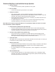
Overview of Key Steps, from Installation through Operation: 1 Install the controller • 2 • 3 Use the panel knock-out pattern guidelines in this guide. Wire the controller Use the connector/wiring information in this guide. Configure the controller • After applying power, use the Configuration Mode to enter the equipment Application Number (from the MINICHEF 2000 Software Selection table), set up the controller and access the thermal optimization functions.
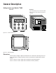
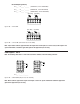
General Description Getting to know your MINICHEF™ 2000 Front view Back view Shown with mating connector terminals installed. Mating connectors and terminals are purchased separately. 2.00 in. IIIIIIIIII IIIIIII IIIIIIIIII IIIIIIII OPER. RANGE 0-80 DEG C 2=OC+ 3=OC35=OC+ 6=OC48=EI1+ 9=ALARM G H A B C D E F 11=EI2+ 12=EI113=L2 24V 14=L1 24V 15=EI2- 3.00 in. NSF c 13 10 7 4 1 14 11 8 5 2 15 12 9 6 3 WATLOW CONTROLS INPUT#1 NOT INPUT#2 NOT TC+ TC- USED TC+ TC- USED 3.00 in.
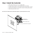
Step 1 Install the Controller • Select sheet metal (16-, 18-, 20- or 22- gauge panel). • For panel knock-out patterns, see subsequent pages of this guide. • Use #6-32 mounting studs x 0.50” length minimum, either pressed or welded. • Install the unit with either a horizontal or vertical mounting collar position. • Install mating connectors to unit. Note: This device should be used in systems that incorporate a separate high limit device for safety.
in . 1. 87 5 in . in . 1. 40 5 in . 1. 00 0 in . 0. 50 0 in . 0. 00 0 in . 0. 50 0 in . 1. 00 0 1. 40 5 1. 87 5 in . Panel Knock-out Pattern for a Mounting Collar in a Horizontal Position 2.535 in. 2.125 in. .875 in. ref 1.660 in. 1.530 in. 1.250 in. ø0.53 in. (6) 0.875 in. ø0.135 in. (10) 0.375 in. 0.125 in. 0.000 in. #6-32 stud (4) minimum recommended length 0.50 in. 0.250 in. 1. 1. 37 37 5 5 in in . . C/L . in . . 5 87 1. 1. 33 8 0 in in . 00 1. 0.
. . 1. 40 5 in . 1. 00 0 in . 0. 50 0 in . 0. 00 0 in . in 0. 50 0 in 1. 00 0 1. 40 5 in . Panel Knock-out Pattern for a Mounting Collar in a Vertical Position 3.000 in. 2.535 in. .875 in. ref 1.660 in. 1.530 in. 1.250 in. ø0.53 in. (6) 0.875 in. ø0.135 in. (10) 0.375 in. 0.000 in. 0.250 in. 0.750 in. . in in 0 5 1. 1. 37 00 . . in in 0 5 00 37 1. 1. . C/L #6-32 stud (4) minimum recommended length 0.50 in. . . in 8 33 1. 1. 00 0 in . . in 0 50 0. 0.
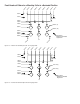
Step 2 Wire the Controller Position the connector with the beveled edges at the top. Not all software applications use or require wiring to all inputs and outputs. For specific information consult the guide for the application you are using. Note: The following illustration is a view of the back of the controller, not of the mating connector. Power Wiring Fuse L1 L2 13 14 13 14 15 10 11 12 7 8 9 4 5 6 1 2 3 Figure 9a — 24VÅ (ac) Low Voltage.
Dual RTD Option (platinum) F2__–2___–____ (100Ω RTD, curve selectable) F2__–3___-____ (500Ω RTD, curve selectable) F2__–4___-____ (1000Ω RTD, curve selectable) Input 1 Wiring S1 Input 2 Wiring S2 1 S1 2 3 S2 4 5 6 Figure 10a — 2-wire RTD. Input 1 Wiring S1 S2 1 2 S3 Input 2 Wiring S1 3 S2 4 S3 5 6 Figure 10b — 3-wire RTD: (will function as a 2-wire RTD). Note: If your chosen software application does not require two sensor inputs, it is not necessary to wire Input 2.
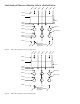
Output 1 Ext. Load Note: The following illustrations are views of the back of the controller, not of the mating connector. 4 1 13 14 15 10 11 12 7 8 9 4 5 6 1 2 3 F2__–_1__–____ Figure 11a — Switched DC Option (5V nominal, 30mA, non-isolated). Fuse L1 Com 4 NO 1 L2 13 14 15 10 11 12 7 8 9 4 5 6 1 2 3 Ext. Load Form A, 0.
Output 2 Ext. Load Note: The following illustrations are views of the back of the controller, not of the mating connector. 10 7 13 14 15 10 11 12 7 8 9 4 5 6 1 2 3 F2__-__1_–____ Figure 12a — Switched DC Option (5V nominal, 30mA, non-isolated). Fuse L1 Com 10 NO L2 7 13 14 15 10 11 12 7 8 9 4 5 6 1 2 3 Ext. Load Form A, 0.
Event Output 1 and Event Output 2 Note: The following illustrations are views of the back of the controller, not of the mating connector. 14 15 13 14 15 10 11 12 10 11 12 7 8 9 7 8 9 4 5 6 4 5 6 1 2 3 1 2 3 Event Output 1 2 Ext. Load 3 F2__-___1-____ Event Output 2 6 5 Ext. Load 13 (switched dc, 5V nominal, 30mA, non-isolated outputs) Figure 13a — Event Outputs.
Step 3 Configure the Controller Overview of Configuration • Get to know the keys and how they function in different modes. • Review configuration and programming procedures in this guide. • Choose applications, functions, parameters and values (see Application Software Selection Table in this guide). • Review the operating instructions (in each application guide). • Get a complete idea of how the application works.
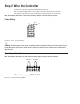
Software Structure The MINICHEF 2000 software uses three modes — Configuration Mode, Programming Mode and Operation Mode — and each mode contains up to three levels of functions, parameters and values. The Operation Mode is the default mode. MINICHEF 2000 [M``1] G A From the Menu Programming Mode, press the Home and Escape keys for two seconds to view the functions. FUNCTIONS Press the Up- or Down-arrow key to scroll through the functions.
MINICHEF 2000 [`idle] G A From the Operation Mode, press the Up- and Downarrow keys for two seconds to view the menus. H C B Edit Enter D F E Home Escape Press the Enter key to return to idle. MENUS Press the Up- or Down-arrow key to scroll through the menus. [M``1] [M``2] [M``3] B Enter D Home • • • Press the Edit key to view the parameters of the selected menu. Press the Home key for three seconds to return to idle. A Edit The display switches between the parameter and its value.
■ 17 NOTES
Watlow Controls Watlow Controls is a division of Watlow Electric Mfg. Co., St. Louis, Missouri, a manufacturer of industrial electric heating products since 1922. Watlow begins with a full set of specifications and completes an industrial product that is manufactured totally inhouse, in the U.S.A. Watlow products include electric heaters, sensors, controls and switching devices.
Specifications (1032) Control Mode 1 • Single and dual heat channels, PID or on/off. • Microprocessor-based, programmable, reverse-acting control outputs. • User-selectable embedded application software defines operation of display, keys, inputs, outputs, timing action. • One-step auto-tuning, WatHelp diagnostics, WatCurve temperature compensation.
Ordering Information (1033) F 2 HA- _ _ _ 1 - _ _AA MINICHEF™ 2000 Cooking controller with numerous food equipment application software sets, single and dual channel on/off or PID temperature regulation, timer and machine-function control, microprocessorbased, programmable, auto-tuning, WatCurve™, WatHelp diagnostics, 24VÅ (ac) power input, agency approved, flush mounted (membrane faceplate supplied by customer).
■ 21 NOTES
Declaration of Conformity WATLOW CONTROLS 1241 Bundy Boulevard Winona, Minnesota 55987 USA 97 MINICHEF 2000 Declares that the following product: English Designation: MINICHEF 2000 Model Number(s): F2(H or U)(A or C)-(1, 2, 3 or 4)(1, 2 or 3)(1, 2 or 3) 1-(0 or 1)(0 or 1)(Any two letters or numbers) Classification: Electronic incorporated Class III temperature controller, Type 2C action, for use in light industrial RatedVoltage: 24V~ (VAC) Rated Frequency: 50/60 Hz Maximum Input Power: 15 Watts Meets the e
Part Numbers & Accessories MINICHEF 2000 Accessories 0836-0442-0000 A001-0298-0000 0238-0679-0000 0830-0479-0000 A001-0249-0001 A001-0249-0002 Sensor Input Mating Connector, (RIACON #31007106), 6-position, quick-connect terminal, screw connection for 28-14 AWG wires, tighten to 7 in/lb Power Supply and I / O Mating Connector Kit. Includes: – 1 AMP #1-640523-0, 15-position, quick-connect terminal – 15 AMP #641300-1 crimp pins Prototyping & Training Membrane Overlay, adhesive-backed, 4.75 in x 4.