
Owner's manual


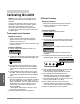


6.4 Watlow MicroDIN
Operations
LED
Indication Symptoms Probable Cause(s)
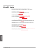
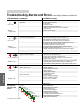
Troubleshooting Alarms and Errors
most likely problems are listed first
Power
• No power. • Power supply switch off
• Fuse blown
Error = off • Breaker tripped
• Safety interlock door switch, etc.
• Separate system limit control may be latched
• Open wiring
(Normal = • Power ≤ 20V‡ (ac/dc)
steady green)
Communications
• Unit will not communicate. • MicroDIN address DIP switch incorrectly set
• MicroDIN baud rate DIP switch incorrectly set
Error = off • MicroDIN unit-to-unit daisy chain disconnected
• Reversed, short or open EIA-485 communications wiring
• EIA-485 converter box incorrectly wired
• Computer COM port incorrectly set up
(Normal = • Communications software setup or address incorrect
pulsing green) • Protocol or parity wrong, not 8, n, 1
• Needs termination and pull-up and pull-down resistors
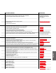
Input Error
• Input is in error condition. • The sensor is improperly wired
• Sensor wiring reversed, shorted or open
Error = steady red • MicroDIN firmware setting does not = actual sensor
• Power ≤ 20V‡ (ac/dc)
• Ambient environmental temperature out of spec for MicroDIN
(Normal = off) • The MicroDIN open loop detect shows a broken sensor
• The calibration offset parameter is set much too high or low
Alarms
• Alarm won’t occur. • Alarm output off
Alarm = • Alarm set points incorrect
steady red • Alarm silenced
• Alarm sides incorrect
• In diagnostics mode
• Alarm won’t clear. • Alarm latched
• Alarm set points incorrect
• Alarm hysteresis incorrect
(Normal = off) • Input in error condition
Unit Errors
Flashing LED Error 4
•
RAM malfunction
Indicator Light Error 5
•
EEPROM data corrupted
Pattern Error 6
•
PROM malfunction
Error 7
•
Logic hardware problem
Error 11
•
New firmware installed
Error 12
•
Calibration data corrupted
Error 13
•
Analog-to-digital hardware failure
Error 14
•
EEPROM hardware problem
Error 15
•
New unit first power up