MICRODIN User’s Manual 97 TOTAL CUSTOMER SATISFACTION 3 Year Warranty ISO 9001 Registered Company Winona, Minnesota USA Communicating Subpanel Temperature Controller User Levels: • New User ....................................................... go to page 1.1 • Experienced User .......................................... go to page 2.1 • Expert User .................................................... go to page 2.1 Installers: • Set-up ............................................................
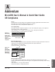
A Addendum MicroDIN User’s Manual & Quick Start Guide CE Compliance Purpose To meet Mark CE requirements, this addendum provides supplemental information to the MicroDIN User’s Manual (W0UD-XUMN Rev A), and the MicroDIN Quick Start Guide (W0UD-XQRN Rev A). Power Supply Rating MicroDIN CE Mark compliance requires an IEC 742 rated power supply. This applies to the following power supply references: User’s Manual: p. 3.2, 3.7 (fig. 3.7e), 3.10 (fig. 3.10), 3.11 (fig. 3.11) and A.14 Quick Start Guide: p.
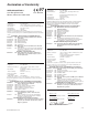
Declaration of Conformity WATLOW CONTROLS 1241 Bundy Boulevard Winona, Minnesota 55987 USA 97 Series MicroDIN Declares that the following product: English Designation: Series MicroDIN Model Number(s): UD 1 A -1CES - (Any four numbers or letters) Classification: Control, Installation Category II, Polution Degree II Rated Voltage: 24 to 28V‡ (ac/dc) Rated Frequency: 50/60 Hz Rated Power Consumption: 5VA maximum Meets the essential requirements of the following European Union Directive(s) using the relevant
Meet the MicroDIN Team TOTAL CUSTOMER SATISFACTION 3 Year Warranty We stand behind our product and are committed to your total satisfaction. Pictured below are some of the people at Watlow who have worked hard to bring you one of the finest industrial temperature controllers available today. Included in the photo are members of the development team, production team, and representatives from our core manufacturing and customer service areas.
NOTE: Details of a “Note” appear here in the narrow margin on the outside of each page. çCAUTION: Details of a “Caution” appear here in the narrow margin on the outside of each page. Safety Information We use note, caution and warning symbols throughout this book to draw your attention to important operational and safety information. A bold text “NOTE” marks a short message in the margin to alert you to an important detail.
TC Table of Contents Chapter 1: Overview ......................................................................... 1.1 Introduction to the MicroDIN Controller .................................. 1.2 Setup Steps ............................................................................. 1.3 Indicator Lights ........................................................................ 1.3 Chapter 2: Communications Setup ................................................... 2.1 Communications Overview ..............
Overview 1 Chapter One: Overview Introduction to the MicroDIN Controller .. 1.2 Setup Steps ............................................. 1.3 Indicator Lights ....................................... 1.3 Watlow MicroDIN 1.
Overview Introduction to the MicroDIN Controller The Watlow MicroDIN controller is a DIN rail-mounted, temperature controller. It uses one input and two outputs, network connections and dozens of parameters to satisfy a broad variety of control needs. The single input can use either a thermocouple or RTD sensor. The single control output provides an open collector or switched dc output signal for a power switching device with a DC input. The single alarm output is an electromechanical relay.
Overview Setup Steps 1. Set up communications. 2. Set the controller’s address and baud speed with the DIP switches on the top panel (see Chapter 2, Communications Setup). The controller uses eight data bits with no parity. 3. Mount the controller (see Chapter 3, Wiring). 4. Wire the controller (see Chapter 3, Wiring). 5. Communicate with MicroDIN via an EIA-485 network with Modbus™ RTU protocol. Indicator Lights Power Green light stays lit when the power is on and the controller is ok.
Overview Notes 1.
Chapter Two: Communications Setup Communications Overview EIA-485 Network ............................... 2.2 Modbus™ Protocol ............................. 2.2 Set Address/Baud Rate .......................2.2 Serial Data Format ............................. 2.2 Wiring Tasks ...................................... 2.2 Communications Software ................. 2.2 EIA-485 Network Elements of a MicroDIN 485 Network 2.3 PC Connection via 232/485 Converter 2.3 Special Case 485 Considerations ....... 2.
Communications Overview EIA-485 Network Communication Setup The MicroDIN uses the EIA-485 (formerly, ÒRS-485Ó) hardware interface to communicate with three wires in a half-duplex configuration, up to 32 remote devices with a master unit on a network up to 4,000 feet long using 14-26 gauge wire. Modbus Protocol The MicroDIN uses Modbusª RTU protocol to read and write to registers that can be viewed or changed from a personal computer.
EIA-485 Network An EIA-485 interface uses three wires in a half-duplex configuration. The EIA-485 standard specifies a T+/R+ line; a T-/R- line; and a common line. EIA-485 interprets a -5 volt signal as a 1, a +5-volt signal as a 0. Up to 32 remote devices can be connected to a master on a multi-drop network up to 4,000 feet long. For industrial networks, EIA-485 offers low impedance, a multiple-device capability, strong noise immunity and the long distance capability.
Special Case 485 Network Considerations If your EIA-485 network does not work, it may require termination resistors. Communication Setup Termination Resistor at the Last MicroDIN çCAUTION: Apply termination and pull-up/pull-down resistors only if necessary to establish data communications. Adding this resistance to a network where it is not required could result in loss of communications and damage to process product. In some cases long distance networks may require termination resistors.
MicroDIN, A Modbus™ Remote Terminal Unit (RTU) The MicroDIN uses Modbus™ RTU (remote terminal unit) protocol to read and write to registers that can be viewed or changed from a personal computer. Sending ASCII text commands to the MicroDIN will not work. Access Via Registers Each MicroDIN parameter has a corresponding Modbus™ register and access privileges. The value of each parameter is stored in a Modbus™ register.
Modbus Register Numbers Communication Setup Address Address Absolute Relative Parameters Absolute Relative Parameters 40001 0 Model Number (Diagnostics) 40602 601 Input Type (Input) 40002 1 Serial Number (Characteristics) 40603 602 Range Low (Input) 40003 2 Serial Number 2 (Characteristics) 40604 603 Range High (Input) 40004 3 Software ID number (Characteristics) 40605 604 Filter Time Constant (Input) 40005 4 Software Revision (Characteristics) 40606 605 Calibration Offset
Configure the communications speed and network address of the MicroDIN controller with the eight-bit DIP switch on the top panel. Set the controller address with the first six switches. Set an address between 1 and 63. The network will not work correctly if any two controllers have the same address. DIP switch 1 sets the left-most binary digit. Switch 6 sets the right-most digit. Record the MicroDIN’s address in erasable marker on the white space on the front of the unit. The seventh switch has no effect.
Note: This table also appears inside the back cover, p. A.19 Required Parameters Setup Order This table provides 1) the correct order of entry, 2) the effect of a parameter change, and 3) a place to document settings. Parameters should be set up in this order.
Serial Data Format Table 2.9a Serial Data Format Data Bits Parity Stop Bit Start Bit 8 None 1 1 MicroDIN Installation Wiring Tasks MicroDIN requires these wiring tasks for a successful installation 1. Wire MicroDIN sensor input. 2. Wire MicroDIN Output 1, the control output. 3. Wire MicroDIN Output 2, the alarm output. 4. Wire MicroDIN power. 5. Connect the MicroDIN communications daisy chain. 6. Wire the 232-to-485 converter; connect to the computer. 7.
Notes Communication Setup 2.
Installation and Wiring ■ 3 Install and Wire Chapter Three: Installation and Wiring Introduction Set DIPs First ......................................3.2 Mount on DIN Rail Tabs...................... 3.2 Wire Unit I/O .......................................3.2 Installation Accessories ..................... 3.2 Mounting the MicroDIN .......................... 3.3 Mounting the MicroDIN on a DIN Rail ... 3.4 MicroDIN RJ-11 and 10-pin Connectors 3.5 Input Wiring ............................................
Introduction For a successful MicroDIN installation you need to cover the tasks cited in the subheads below. If you do all these things and the MicroDIN doesn’t work, go to the troubleshooting chart in Chapter 6. Set DIP Switch First If you haven’t done it already, set the controller’s address and baud speed with the DIP switches on the top of the unit (see Chapter 2, Communications Setup). The controller uses eight data bits with no parity, and 1 stop bit.
Mounting the MicroDIN To mount a MicroDIN on a DIN rail, hook the upper lip of the rail mounting bracket onto the rail and press the controller down until the bottom lip of the mount snaps onto the rail. To remove, as you push the back of the controller down lift the front up until the bottom lip unsnaps from the rail. To mount a MicroDIN on a panel, use the dimensions below to drill screw holes for the mounting bracket. bracket for panel mounting (#6 screw or m3.5 required) .
Mounting the MicroDIN on a DIN rail To Mount MicroDIN 1. Push unit in and down to catch rail hook on top of rail. 2. Rotate bottom of unit in toward rail. ① 3. Rail clasp will audibly “snap” into place. If the MicroDIN does not snap into place, check to see if the rail is bent. Install and Wire Figure 3.4a Mounting a MicroDIN controller on a DIN rail. ➂ "Snap" ➁ To Dismount MicroDIN 1. Press down on back of controller until the bottom hook clears the rail. ① 2.
MicroDIN RJ-11 and 10-pin Connectors WARNING: To avoid potential electric shock, use National Electric Code (NEC) safety practices when wiring and connecting this unit to a power source and to electrical sensors or peripheral devices. Failure to do so could result in injury or death. Figure 3.5 - Bottom view of MicroDIN case with connector assignments. The alarm output is an electromechanical relay. See the Appendix for information on sensor ranges and specifications.
Input Wiring Figure 3.6a — MicroDIN Isolation Diagram Power Supply Safety Isolation Logic and Input Outputs UL/CE Comms 500V Noise Isolation Install and Wire Control Output Alarm Figure 3.6b — Control Input, Thermocouple 1 2 3 4 5 6 7 8 9 10 + - Figure 3.6c — Control Input, 2-wire RTD 1 2 3 4 5 6 7 8 9 10 S1 S3 Figure 3.6d — Control Input, 3-wire RTD 1 2 3 4 5 6 7 8 9 10 S1 S2 S3 3.
Output and Power Wiring Figure 3.7b — Control Output, Open Collector with External Power Supply dc + dc C O M 1 2 3 4 5 6 7 8 9 10 1 2 3 4 5 6 7 8 9 10 + External External External Switching Load Device External Switching Device Load - - + + Power Supply 60V max. 1A max. Figure 3.
Communications Wiring Figure 3.8a - MicroDIN communications daisy chain via RJ-11 connectors.
Special EIA-485 Network Considerations Figure 3.9 a- Termination for MicroDIN; RJ-11 phone plug with 120Ω resistor across C and D ABCD RJ-11 Terminals C (green) and D (yellow) 120Ω Plug terminator into open socket in MicroDIN controller furthest from computer, the last unit on the network. Figure 3.9b Termination for EIA-232/EIA-485 Converter with pull-up and pull-down resistors. +5V Converter box termination with pull-up and pull-down resistors.
Wiring Examples Ó Install and Wire WARNING: To avoid potential electric shock, use National Electric Code (NEC) safety practices when wiring and connecting this unit to a power source and to electrical sensors or peripheral devices. Failure to do so could result in injury or death.
Ó Figure 3.11 System wiring example, ladder diagram.
Notes Install and Wire 3.
4 Chapter Four: Features Features The System Auto-tune ........................................... 4.2 Power Limit ....................................... 4.3 Input Calibration Offset ............................... 4.4 Filter Time Constant ........................... 4.5 Sensor Selection ................................ 4.6 Range Low and Range High .............. 4.6 Control Methods On/Off ................................................ 4.7 Proportioned Control ......................... 4.
The System Auto-tune Auto-tuning allows the controller to explore the responsiveness of the system in order to determine an effective set of parameters for PID control. To do this it crosses an auto-tune set point five times, then controls at the normal set point using the new parameters. Use Auto-tune Set Point (PID Group) to select the temporary set point, as a percentage of the normal set point, that the controller will tune to. Initiate or cancel the auto-tune process with Auto-tune (PID Group).
Power Limit A high side power limit and low side power limit set the maximum output power within two ranges A low side power limit limits the output to a percentage of the maximum output power while the process temperature or value is below the power limit set point. The high side power limit limits the output to a percentage of the maximum output power while the process temperature or value is above the power limit set point.
Input Calibration Offset Calibration offset allows a device to compensate for an inaccurate sensor, lead resistance or other factors that affect the input value. A positive offset increases the input value, and a negative offset decreases the input value. The input offset value can be viewed or changed with Calibration Offset (Input Group). Negative Calibration Offset will compensate for the difference between the Sensor Reading and the Actual Temperature.
Filter Time Constant A time filter smooths an input signal by sampling the input at designated time intervals. Either the viewed value or both the viewed and control values can be filtered. View or change the time filter with Filter Time Constant (Input Group). A positive value affects only the viewed values. A negative value affects both the viewed and control values. The filter is a single pole low pass.
Sensor Selection You need to configure a controller to match the input device, which is normally a thermocouple or RTD. When you select an input device the controller automatically sets the input linearization to match the sensor. It also sets high and low limits, which in turn limit the range high and range low values. Use Sensor Type and Input Type (Input Group) to select the appropriate sensor.
Control Methods On/Off Control On/off control switches the output either full on or full off, depending on the input, set point and hysteresis values. The hysteresis value creates a buffer zone that increases the time interval that the output is off or on. With hysteresis set to 0 the process value would stay closer to the set point, but the output would switch on and off more frequently, causing “chattering.” Set hysteresis with Output Hysteresis (PID Group).
Proportional Control Some processes need to maintain a temperature or process value closer to the set point than on/off control can provide. Proportional control provides closer control by adjusting the output when the temperature or process value is within a proportional band. When the value is in the band, the controller adjusts the output based on how close the process value is to the set point: the closer to set point the lower the output.
Proportional plus Integral (PI) Control The droop caused by proportional control can be corrected by adding integral (reset) control to the system. When the system has settled down the integral (reset) value is tuned to bring the temperature or process value closer to the set point. However, this may increase the overshoot that occurs at startup or when the set point is changed. Used more with fast, high loss loads. View or change the integral or reset value with Integral or Reset.
Proportional plus Integral plus Derivative (PID) Control Use derivative (rate) control to minimize the overshoot in a PI-controlled system. Derivative (rate) adjusts the output based on the rate of change in the temperature or process value. Used more with slow, lagging loads. View or change derivative or rate with Derivative or Rate (PID Group). To only view the derivative control value use Derivative Term (PID Group). Reduced Overshoot Set Point Temperature Proportional Band Features Time Figure 4.
Alarms An alarm takes some action, usually notifying an operator, when the process temperature leaves a defined range. A user can configure how and when an alarm is triggered and whether it turns off automatically when the alarm condition is over. High Side Alarm Range Alarm High Set Point Temperature Alarm Hysteresis Normal Operating Range Alarm Hysteresis Alarm Low Set Point Features Low Side Alarm Range Time Figure 4.
Process or Deviation Alarms A process alarm uses one or two fixed set points to define an alarm condition. A deviation alarm uses one or two set points that are defined relative to the control set point. High and low alarm set points are calculated by adding and/or subtracting offset values from the control set point. If the set point changes, the alarm set points automatically change with it.
Alarm Silencing Alarm silencing has two uses: 1. It is often used to allow a system to warm up after it has been started up. With alarm silencing on, an alarm is not triggered when the process temperature is initially lower that the alarm low set point. The process temperature has to enter the normal operating range beyond the hysteresis zone in order to activate the alarm function. 2. Alarm silencing also allows the operator to disable the alarm output while the controller is in an alarm state.
Errors Panel Indicator Lights Figure 4.
Bumpless Transfer When the sensor opens (fails), the MicroDIN switches from automatic to manual operation. When transferring from automatic to manual operation, the control output, or outputs, remain stable — a bumpless, or smooth, transition.
Notes Features 4.
5 Chapter Five Learn the Parameters System Group ............5.2 PID Group................5.13 Characteristics Group..5.25 Input Group ...............5.4 Input Actual (100) .......................... 5.4 Input Error (101) ............................ 5.4 Sensor Type (600) ........................... 5.5 Input Type (601) ............................. 5.5 Range Low (602) ............................. 5.6 Range High (603)............................ 5.6 Calibration Offset (605) ................. 5.
System Group continued System Group Monitor Ambient (CJC) Temperature .................... 5.2 Use Non-volatile Memory ................................. 5.2 Setup Units Type ................................................. 5.3 C or F ......................................................... 5.3 Decimal Point ............................................ 5.3 ç CAUTION: Avoid writing continuously to EEPROM memory.
System Group continued System Group – Setup Units Type • Select US or SI units of measurement. • Read/write • Modbus: 900 Range 0: US (reciprocate integral term) 1: SI (reciprocate integral term) Default 0: US Active always Affects Propband, Integral and Reset (PID Group) converts Reset and Integral (changes span to degrees or vice versa) C or F Decimal Point • Sets the position of the decimal point for input readings.
Input Group Monitor Input Actual ............................................... 5.4 Input Error ................................................ 5.4 Setup Sensor Type ............................................... 5.5 Input Type ................................................. 5.5 Range Low ................................................. 5.6 Range High ................................................ 5.6 Calibration Offset ...................................... 5.6 Filter Time Constant ................
Input Group continued Input Group – Setup Sensor Type • Select the input sensor type. • Read/write • Modbus: 600 Range 0: thermocouple 1: RTD Default 0: thermocouple Active always Affects Changes Input Type (Input Group) to J for thermocouple, DIN for RTD, and defaults temperature related parameters. • Set the linearization for the input sensor.
Input Group continued Range Low • Set the input range low. This setting is the lowest value that the set point can have. • Read/write • Modbus: 602 Range see Sensor Table in the Appendix for sensor ranges and defaults Default see Sensor Table in the Appendix for sensor ranges and defaults Active always Affects Set Point (Operation Group) limits the set point to the range between Range Low and Range High (Input Group) Range High • Set the input range high.
Input Group continued Filter Time Constant • Set the filter time for the input, in seconds. This smooths out a rapidly changing input signal. Positive values affect the monitor readings only. Negative values affect both the monitor readings and the control values. • Read/write • Modbus: 604 Range -60.0 to 60.0 Default 0.0 Active always Input Error Action Parameters • Select how the controller responds to an input error.
Control Output Group Monitor Output Power .............................................. 5.8 Control Output Hardware .......................... 5.8 Setup Control Output Function ............................ 5.8 Power Limit Set Point ................................. 5.9 High Side Power .......................................... 5.9 Low Side Power ........................................... 5.9 Fixed Manual Output ................................ 5.10 ç CAUTION: Avoid writing continuously to EEPROM memory.
Control Output Group continued Range 0: heat 1: cool Default 0: heat Active always Affects Manual Output Power (Operation Group) determines heat or cool values. High Side Power, Low Side Power or Fixed Manual Output (Control Output Group) changes range Power Limit Set Point • Select the set point that High Side Power and Low Side Power (Control Output Group) will use to limit the control output range.
Control Output Group continued Low Side Power • Set the maximum allowed power below the Power Limit Set Point (Control Output Group). • Read/write • Modbus: 715 Range heat: 0.0 to 100.0 cool: -100.0 to 0.0 Default heat: 100.0 cool: -100.0 Active always Affected by Changing Control Output Function (Control Output Group) changes range Fixed Manual Output Parameters • Select the initial control output power to take effect when the controller is switched to manual mode by either the user or an error.
Control Output Group continued Operation Group Monitor Operation Mode ......................................... 5.11 Use Operation Mode ......................................... 5.11 User Set Point ........................................... 5.12 Manual Output Power .............................. 5.12 CAUTION: Avoid writing continuously to EEPROM memory. Continuous writes may result in premature control failure, system downtime and damage to processes and equipment.
Operation Group continued User Set Point • Change or monitor the control set point.
PID Group Monitor PID Output Power ..................................... 5.13 Initiate Auto-tune ...................................... 5.14 Setup Auto-tune Set Point .................................. 5.13 Proportional Band ..................................... 5.14 Integral ...................................................... 5.14 Reset ........................................................... 5.15 Derivative .................................................. 5.15 Rate ................................
PID Group continued Initiate Auto-tune • Initiate or cancel an auto-tune. • Read/write • Modbus: 305 Range 0: off or cancel an auto-tune in progress 1: initiate an auto-tune Default 0: off Active if Operation Mode (Operation Group) is set to auto Affected by Changing Operation Mode (Operation Group) available when mode is set to auto PID Group – Setup Proportional Band Parameters • Set the proportional band for PID control. See Chapter 4 for information about PID control.
PID Group continued about PID control. • Read/write • Modbus: 502 Range 0.00 to 99.99 minutes per repeat Default 0.00 Active if Propband (PID Group) is not set to 0 and Units Type (System Group) is set to US Affected by Changing Units Type (System Group) will convert Integral to Reset. Derivative • Set the derivative time for PID control. See Chapter 4 for information about PID control. • Read/write • Modbus: 503 Range 0.00 to 9.99 minutes Default 0.
PID Group continued Cycle Time • Set the control output cycle time in seconds. • Read/write • Modbus: 506 Range 0.1 to 60.0 seconds Default 2.0 Active if Propband (PID Group) is not set to 0 and Units Type (System Group) is set to US Control Output Hysteresis • Set the control output switching hysteresis. • Read/write • Modbus: 507 Range 1 to 9999°F or °C Default 3 Active only if Propband is set to 0 Parameters 5.
PID Group continued Alarm Output Group Monitor Alarm Condition ........................................ 5.17 Alarm Output Hardware .......................... 5.17 Use Clear Alarm ............................................... 5.18 Silence Alarm ............................................ 5.18 Setup Alarm Low ................................................. 5.18 Alarm High ................................................ 5.19 Alarm Output Function ............................ 5.19 Alarm Type ............
Alarm Output Group continued Alarm Output Hardware • Read the alarm output hardware type. • Read only • Modbus: 17 Range 1: mechanical relay Default 1 Active always Alarm Output Group – Use Clear Alarm ON • Alarm will clear if alarm condition is resolved • Read/write • Modbus: 331 Range 0: no action 1: try to clear a latched alarm Default 0 (always reverts to 0 after a write) Active if Alarm Latching Mode (Alarm Output Group) is set to yes Silence Alarm ON Parameters • Silence the alarm manually.
Alarm Output Group continued Alarm Output Group – Setup Alarm Low • Set the low alarm set point. • Read/write • Modbus: 321 Range process: sensor range low to Alarm High (Alarm Output Group) deviation: -1999 to -1 Default process: sensor range low deviation: -1999 Active if Alarm Output Function (Alarm Output Group) is set to alarm Affected by Sensor Type (Input Group) determines range of setting and default. Input Type (Input Group) determines range of setting and default.
Alarm Output Group continued Alarm Output Function • Turn the alarm output on or off. • Read/write • Modbus: 717 Range 0: off 1: alarm Default 0: off Active always Alarm Type Parameters • Select alarm type. A process alarm responds when the temperature leaves a fixed range. A deviation alarm responds when the temperature deviates from the set point by a set number of degrees.
Alarm Output Group continued Range 0: both 1: high side only 2: low side only Default 0: both Active if Alarm Output Function (Alarm Output Group) is set to alarm Alarm Latching Mode • Turn alarm latching on or off. When latching is active, the alarm will remain on after the alarm condition ends. It must be turned off manually. • Read/write • Modbus: 721 Range 0: no 1: yes Default 0: no Active if Set Alarm Output Function (Alarm Output Group) is set to alarm • Turn alarm silencing on or off.
Error Group continued Error Group ç CAUTION: Avoid writing continuously to EEPROM memory. Continuous writes may result in premature control failure, system downtime and damage to processes and equipment. See Disable Nonvolatile Memory (System Group). Monitor Open Loop Error ........................................ 5.22 Open Loop Detect ...................................... 5.22 Input Error ................................................ 5.22 System Error ............................................. 5.
Error Group continued Input Error (see also Input Group) • Monitor the input error status. • Read only • Modbus: 101 Range 0: no error 1: analog-to-digital signal under range 2: sensor under range 3: sensor over range 4: analog-to-digital over signal range Default none Active always System Error Parameters • Read the system error status.
Error Group continued Error Group – Setup Input Error Action (see also Input Group) • Select how the controller responds to an input error. • Read/write • Modbus: 902 Range 0: bumpless transfer (control output power remains constant, Chapter 4) 1: switch to the Fixed Manual Output (Control Output Group) setting 2: shut off output Default 0: bumpless transfer Active always Error Clearing Mode Parameters • Set the error clearing mode.
Characteristics Group continued Characteristics Group Date of Manufacture ................................. 5.25 Ship Date ................................................... 5.25 Serial Number 1 ........................................ 5.25 Serial Number 2 ........................................ 5.26 Software ID Number ................................. 5.26 Software Revision ...................................... 5.26 Date Of Manufacture • Read the manufacture date as week/year (WWYY).
Characteristics Group continued Serial Number 2 • Read the last four digits of the serial number. • Read only • Modbus: 002 Range 0-9999 Default 0 Active always Software ID Number • Read the software ID number. • Read only • Modbus: 003 Range 0 to 9999 Default none Active always Software Revision Parameters • Read software revision number. • Read only • Modbus: 004 Range 0.00 to 99.99 Default none Active always 5.
Diagnostics Group continued Diagnostics Group Model Number ........................................... 5.27 Ambient (CJC) A-to-D Counts .................. 5.27 Input A-to-D Counts .................................. 5.27 RTD Lead Compensation A to D Counts . 5.28 RTD Lead Resistance ................................ 5.28 Proportional Term ..................................... 5.28 Integral Term ............................................. 5.28 Derivative Term ......................................... 5.
Diagnostics Group continued RTD Lead Compensation Analog-to-Digital Counts • Reads the raw, RTD lead compensation, analog-to-digital converter counts. • Read only • Modbus: 1502 Range 0 to 65535 Default none Active always RTD Lead Resistance • Reads the measured RTD lead resistance in 0.01 ohms. • Read only • Modbus: 1503 Range 0.00 to 99.99 Default none Active always Proportional Term Parameters • Monitor the proportional term. See Chapter 4 for information about PID control.
Diagnostics Group continued Derivative Term • Monitor the derivative term. See Chapter 4 for information about PID control. • Read only • Modbus: 207 Range -100.0 to 100.0 Default none Active always Enter Diagnostics Mode (Set) • Enter the diagnostics mode to test indicator lights and outputs and to enter the calibration mode.
Calibration Group continued NOTE: See page 6.6 for the calibration procedures. Calibration Group Enter Calibration Mode ............................ 5.30 Calibration Commands ............................. 5.30 Restore Factory Calibration .................... 5.30 Reset Factory Defaults............................... 5.31 Enter Calibration Mode ç CAUTION: Avoid writing continuously to EEPROM memory.
Calibration Group continued Restore to Factory Calibration (Set) • Restore factory calibration values from the backup memory. • Write • Modbus: 1601 Range 0: no action 1: restore factory calibration Default 0 (always reads 0) Active if the controller is in the calibration mode Reset Factory Defaults (Set) Parameters • Reset all parameters to factory values.
Notes Parameters 5.
6 Chapter Six: Operation and Calibration Operations MicroDIN Startup ..................................... 6.2 MicroDIN Shutdown ................................ 6.3 Troubleshooting Alarms and Errors ......... 6.4 Calibrating the MicroDIN ......................... 6.6 Watlow MicroDIN 6.
MicroDIN Startup Starting the Watlow MicroDIN for either one zone or several in any thermal system requires successful completion of this checklist: • Units securely mounted (see p. 3.3, 3.4) • Proper sensor placement (see Watlow Application Guide) • Correct input wiring (see p. 3.5, 3.6) • Correct communications wiring (see p. 2.2 - 2.4, 3.5, 3.8, 3.9) • Correct fusing installed (see p. 3.10, 3.11) • Correct limit protection installed (see p. 3.10, 3.11) • Correct power wiring (see p. 3.5, 3.7, 3.10, 3.
MicroDIN Shutdown Shutting down a Watlow MicroDIN-controlled thermal system for an optimum restart requires attention to the following list: • Updating all systems and controllers parameter records. • Securing any system safety interlocks or peripherals • Protecting the system from unnecessary exposure to moisture or corrosive environments or dust Operations • Anticipating the next startup and associated issues. Watlow MicroDIN 6.
Troubleshooting Alarms and Errors most likely problems are listed first LED Indication Symptoms • No power. Error = off (Normal = steady green) • Unit will not communicate. Error = off (Normal = pulsing green) • Input is in error condition. Error = steady red (Normal = off) • Alarm won’t occur. Alarm = steady red • Alarm won’t clear. Operations (Normal = off) Flashing LED Indicator Light Pattern Error 4 Error 5 Error 6 Error 7 Error 11 Error 12 Error 13 Error 14 Error 15 6.
Corrective Action Reference • Check switches, fuses, breakers, interlocks, limits, connectors, etc. for energized condition and proper connection • See Watlow Publication #COR-AG-76, “Putting it All Together.” • Measure power upstream for required level • Check wire size • Check for bad connections • See p. 3.7, 3.10, 3.11, A.
Calibrating MicroDIN Note: For information on writing Modbus™ RTU communications software for MicroDIN, see the Appendix. To enter the calibration mode, first enter the diagnostics mode; send value 1789 to register 1512. Once in Diagnostics mode, to enter calibration mode, send 1415 to register 1600. To restore factory calibrations settings, send value 1 to register 1601.
A Appendix Appendix Modbus™ RTU ............................................. A.2 Glossary ...................................................... A.8 Declaration of Conformity ....................... A.12 Specifications ............................................ A.13 Ordering Information .............................. A.15 Index ......................................................... A.16 Parameter Index ...................................... A.18 Required Parameter Setup Order ........... A.
Modbus Remote Terminal Unit (RTU) Modbus RTU enables a computer or PLC to read and write directly to registers containing the controller’s parameters. With it you could read all 141 of the controller’s parameters with five read commands. Because of the wide array of choices available for setting up a MicroDIN controller, only a subset of the prompts contain parameters in a given situation. This manual explains the interrelations between prompts.
Packet format: | nn | nn | nn nn… | nn nn | ∆ ∆ ∆ ∆ ∆ ∆ address command registers and/or data CRC Read Multiple Registers Command (0x03 or 0x04) This command returns from 1 to 32 registers.
Example: Read register 0 (model number) of the controller at address 1. Sent: 01 03 00 00 00 01 84 0A Received: 01 03 02 03 DC B9 2D Message: 988 (0x03DC). Example: Read register 1 and 2 (Process 1 and 2 values) of controller at address 5. Sent: 05 03 00 01 00 02 94 4F Received: 05 03 04 00 64 00 C8 FF BA Message: 100 (0x0064) and 200 (0x00C8). Write to a Single Register Command (0x06) This command writes a parameter to a single register. The controller will echo back the command.
Packet sent to controller: | nn | 10 | nn nn | 00 01 | 02 | nn nn | nn nn | ∆ ∆ ∆ ∆ ∆ ∆ ∆ ∆ ∆ ∆ ∆ controller address (one byte) write to multiple registers command (0x10) starting register high byte starting register low byte number of registers to write high byte (0x00) number of registers to write low byte (must be 0x01) number of data bytes (must be 0x02) data high byte data low byte CRC low byte CRC high byte Packet returned by controller: | nn | 10 | nn nn | 00 01 | nn nn | ∆ ∆ ∆ ∆ ∆ ∆ ∆ ∆ controller a
Example: Run loop back test on controller at address 40 (0x28). Sent: 28 08 55 66 77 88 31 B7 Received: 28 08 55 66 77 88 31 B7 Exception Responses When a controller cannot process a command it returns an exception response and sets the high bit (0x80) of the command.
Cyclical Redundancy Checksum (CRC) Algorithm This C routine, calc_crc(), calculates the cyclical redundancy checksum, CRC, for a string of characters. The CRC is the result of dividing the string by 0xA001. Modbus applications calculate the packet’s CRC then append it to the packet.
Glossary annunciator — A visual display that uses pilot lights to indicate the former or existing condition of several items in a system. burst fire — A power control method that repeatedly turns on and off full ac cycles. Also called zero-cross fire, it switches close to the zero-voltage point of the ac sine wave. Variable-time-base burst fire selectively holds or transits ac cycles to achieve the desired power level. See zero cross.
a form A or form B contact. hysteresis — A change in the process variable required to re-energize the control or alarm output. Sometimes called switching differential. integral — Control action that automatically eliminates offset, or droop, between set point and actual process temperature. See auto-reset. integral control (I) — A form of temperature control. The I of PID. See integral. isolation — Electrical separation of sensor from high voltage circuitry.
proportional control — A control using only the P (proportional) value of PID control. range — The area between two limits in which a quantity or value is measured. It is usually described in terms of lower and upper limits. rate — Anticipatory action that is based on the rate of temperature change, and compensates to minimize overshoot and undershoot. See derivative. rate band — A range in which the rate function of a controller is active. Expressed in multiples of the proportional band. See PID.
transmitter — A device that transmits temperature data from either a thermocouple or a resistance temperature detector (RTD) by way of a two-wire loop. The loop has an external power supply. The transmitter acts as a variable resistor with respect to its input signal. Transmitters are desirable when long lead or extension wires produce unacceptable signal degradation.
Declaration of Conformity WATLOW CONTROLS 1241 Bundy Boulevard Winona, Minnesota 55987 USA 97 Series MicroDIN Declares that the following product: English Designation: Series MicroDIN Model Number(s): UD 1 A -1CES - (Any four numbers or letters) Classification: Control, Installation Category II, Polution Degree II Rated Voltage: 24 to 28V‡ (ac/dc) Rated Frequency: 50/60 Hz Rated Power Consumption: 5VA maximum Meets the essential requirements of the following European Union Directive(s) using the relevant
Specifications: W0UD-XSPN Rev A01 Control Mode • Microprocessor-based, user selectable control modes • Single input, single output • Heat or cool auto-tuning Output #1: User selectable • ON/OFF; P, PI, PD, PID heat or cool action adjustable switching differential: 1 to 9999 or 0.1 to 999.9°F or °C • Proportional band: 0 to 9999, or 0.0 to 999.9°F or °C • Integral: 0.00 to 99.99 minutes per repeat • Reset: 0.00 to 99.99 repeats per minute • Derivative/Rate: 0.00 to 9.99 minutes • Cycle Time: 0.1 to 60.
Primary Control Output (heating or cooling) • Output update rate: 10 per second, 10Hz (maximum) Internal Load Switching (nominal): Switched dc (isolated) signal, 22 to 28VÎ (Vdc), current limited @ 30mA Overload current and short circuit protection External Load Switching (maximum): • Open Collector 60VÎ (Vdc) @ 1A Alarm Output • Output update rate 2 per second (2Hz) • Electromechanical relay, Form A, 2A @ 30VÎ (Vdc) or 240VÅ(Vac), • Alarm output can be latching or non-latching, and process or deviation wi
Ordering Information MicroDIN Controller W0UD-XMNN Rev A00 DIN Rail Mount Temperature Controller with no operator interface and EIA-485 Modbus™ RTU Serial Communications. To order, complete the code number to the right with the information below: UD1A-1CES- _ _ _ _ Hardware 1A = Single channel, low voltage Input 1 = Type B, C, D, E, J, K, N, PT2, R, S, T, 1°RTD, 0, 1°RTD (JIS and DIN) Control Output C = Switched (DC), logic signal, isolated.
Index 10-pin connector 3.5 A accuracy A.14 affects table 2.8 Alarm Active Sides 5.20 Alarm Condition 5.17 Alarm High 5.19 Alarm Hysteresis 4.11, 5.20 alarm latching 4.12 Alarm Latching Mode 5.20 - 5.21 Alarm Logic 5.21 Alarm Low 5.18 - 5.19 alarm output A.14 Alarm Output Function 5.19 Alarm Output Group 5.17 - 5.21 Alarm Output Hardware 5.17 - 5.18 alarms 4.11 - 4.13 alarm set points 4.11 alarm silencing 4.13 Alarm Silencing Mode 5.21 Alarm Type 5.19 - 5.20 Ambient Temperature 5.
proportional control 4.8 proportional integral control 4.9 proportional integral derivative control 4.10 R Range High 4.6, 5.6 Range Low 4.6, 5.6 Rate 5.15 Reset 5.15 Restore Factory Calibration 5.30 5.31 Restore Factory Defaults 5.31 RTD lead compensation 5.28 RTD lead resistance 5.28 W warranty information back cover WatLink 2.9 wiring 3.2 - 3.10 write to a single register A.4 write to multiple registers A.4 - A.5 writing a modbus application A.2 S safety agency approvals A.
Parameter Index (alphabetical order) H A Alarm Active Sides 5.20 Alarm Condition 5.17 Alarm High 5.19 Alarm Hysteresis 4.11, 5.20 Alarm Latching Mode 5.20 - 5.21 Alarm Logic 5.21 Alarm Low 6.21 - 5.18 - 5.19 Alarm Output Function 5.19 Alarm Output Group 5.17 - 5.21 Alarm Output Hardware 5.17 5.18 Alarm Silencing Mode 5.21 Alarm Type 5.19 - 5.20 Ambient Temperature 5.2 Analog-to-digital Counts 5.27 5.28 Auto-tune Set Point 5.13 C Calibration Commands 5.30 Calibration Group 5.30 - 5.31 Calibration Mode 5.
Required Parameters Setup Order also found on page 2.8 This table provides 1) the correct order of entry, 2) the affect of a parameter, and 3) a place to document your settings.
How to Reach Us TOTAL Contact Your Authorized Watlow Distributor is: CUSTOMER SATISFACTION 3 Year Warranty Quality and Mission Statement: Watlow Controls will be the world’s best supplier of industrial temperature control products, services, and systems by exceeding our customers’, employees’, and shareholders’ expectations. • or Phone: (507) 454-5300. • Fax: (507) 452-4507. • For technical support, ask for an Applications Engineer. • To place an order, ask for Customer Service.