Wa t l o w M i c r o D I N Q u i c k S t a r t G u i d e MicroDIN Quick Start Guide Communicating Subpanel Temperature Controller Watlow Winona 1241 Bundy Blvd., P.O. Box 5580, Winona, MN 55987-5580 Phone: (507) 454-5300, Fax: (507) 452-4507 www.watlow.com 0600-0011-0002 Rev B February 2003 $5.
Watlow MicroDIN Quick Start Guide Introduction to the MicroDIN Controller The Watlow MicroDIN controller is a DIN rail-mounted, temperature controller. It uses one input and two outputs, network connections and dozens of parameters to satisfy a broad variety of control needs. The single input can use either a thermocouple or RTD sensor. The single control output provides an open collector or switched dc output signal for a power switching device with a DC input.
Watlow MicroDIN Quick Start Guide Setup Steps 1. Set up communications. 2. Set the controller’s address and baud speed with the DIP switches on the top panel (see page 6). The controller uses eight data bits with no parity. 3. Mount the controller (see pages 9 and 10). 4. Wire the controller (see pages 12-14). 5. Communicate with MicroDIN via an EIA-485 network with Modbus™ RTU protocol.
Watlow MicroDIN Quick Start Guide Communications Overview EIA-485 Network The MicroDIN uses the EIA-485 (formerly, “RS-485”) hardware interface to communicate with three wires in a half-duplex configuration, up to 32 remote devices with a master unit on a network up to 4,000 feet long using 14-26 gauge wire. Modbus™ Protocol The MicroDIN uses Modbus™ RTU protocol to read and write to registers that can be viewed or changed from a personal computer.
Watlow MicroDIN Quick Start Guide Modbus™ Register Numbers Address Address Absolute Relative Parameters Absolute Relative Parameters 40001 0 Model Number (Diagnostics) 40601 600 Sensor Type (Input) 40002 1 Serial Number (Characteristics) 40602 601 Input Type (Input) 40003 2 Serial Number 2 (Characteristics) 40603 602 Range Low (Input) 40004 3 Software ID number (Characteristics) 40604 603 Range High (Input) 40005 4 Software Revision (Characteristics) 40605 604 Filter Tim
Watlow MicroDIN Quick Start Guide MicroDIN DIP Switches Set Address/Baud Rate Configure the communications speed and network address of the MicroDIN controller with the eight-bit DIP switch on the top panel. Set the controller address with the first six switches. Set an address between 1 and 63. The network will not work correctly if any two controllers have the same address. DIP switch 1 sets the left-most binary digit. Switch 6 sets the right-most digit.
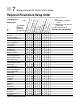
Watlow MicroDIN Quick Start Guide Required Parameters Setup Order This table provides 1) the correct order of entry, 2) the effect of a parameter change, and 3) a place to document settings. Parameters should be set up in this order.
Watlow MicroDIN Quick Start Guide Serial Data Format Configure your computer’s COM1 or COM2 (communications) port data format to match the MicroDIN’s settings in the table below. Table 8a Serial Data Format Data Bits Parity Stop Bit Start Bit 8 None 1 1 MicroDIN Installation Wiring Tasks MicroDIN requires these wiring tasks for a successful installation 1. Wire MicroDIN sensor input. 2. Wire MicroDIN Output 1, the control output. 3. Wire MicroDIN Output 2, the alarm output. 4.
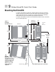
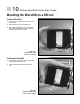
Watlow MicroDIN Quick Start Guide Mounting the MicroDIN To mount a MicroDIN on a DIN rail, hook the upper lip of the rail mounting bracket onto the rail and press the controller down until the bottom lip of the mount snaps onto the rail. To remove, as you push the back of the controller down lift the front up until the bottom lip unsnaps from the rail. To mount a MicroDIN on a panel, use the dimensions below to drill screw holes for the mounting bracket.
Watlow MicroDIN Quick Start Guide Mounting the MicroDIN on a DIN rail To Mount MicroDIN 1. Push unit in and down to catch rail hook on top of rail. 2. Rotate bottom of unit in toward rail. ① 3. Rail clasp will audibly “snap” into place. If the MicroDIN does not snap into place, check to see if the rail is bent. Figure 10a Mounting a MicroDIN controller on a DIN rail ➂ "Snap" ➁ To Dismount MicroDIN 1. Press down on back of controller until the bottom hook clears the rail. ① 2.
Watlow MicroDIN Quick Start Guide MicroDIN RJ-11 and 10-pin Connectors The MicroDIN 10-pin screw terminal connector, on the bottom of the case, links it to its power supply, control input, control output and alarm output. Use 26- to 14-gauge wire to connect to the plug terminals. The alarm output is an electromechanical relay. See the Appendix for information on sensor ranges and specifications. See Chapter 5: Parameters for information about software configuration.
Watlow MicroDIN Quick Start Guide Input Wiring Figure 12a — MicroDIN Isolation Diagram Power Supply Safety Isolation Logic and Input Outputs UL/CE Comms 500V Noise Isolation Control Output Alarm Figure 12b — Control Input, Thermocouple 1 2 3 4 5 6 7 8 9 10 + - Figure 12c — Control Input, 2-wire RTD 1 2 3 4 5 6 7 8 9 10 S1 S3 Figure 12d — Control Input, 3-wire RTD 1 2 3 4 5 6 7 8 9 10 S1 S2 S3
Watlow MicroDIN Quick Start Guide Output and Power Wiring Figure 13b — Control Output, Open Collector with External Power Supply dc + dc C O M dc + dc C O M Figure 13a — Control Output, Switched DC with Internal Power Supply 1 2 3 4 5 6 7 8 9 10 1 2 3 4 5 6 7 8 9 10 + External External Switching Load Device External External Switching Load Device - - Power + + 42V max. Supply 1A max.
Watlow MicroDIN Quick Start Guide Communications Wiring Figure 14a- MicroDIN communications daisy chain via RJ-11 connectors MicroDIN MicroDIN MicroDIN MicroDIN Temperature Controller Temperature Controller Temperature Controller Temperature Controller Power Power Power Comms Comms Comms Comms Control Output Control Output Control Output Control Output Alarm Alarm Address Alarm Input Error Input Error Note: If your network doesn’t function, see Special 485 Network Consideration
Watlow MicroDIN Quick Start Guide Special EIA-485 Network Considerations If your MicroDIN network doesn't work, it may need termination and pull-up and pull-down resistors; wire them per the diagrams below. Figure 15 a- Termination for MicroDIN; RJ-11 phone plug with 120Ω resistor across C and D ABCD RJ-11 Terminals C (green) and D (yellow) 120Ω Plug terminator into open socket in MicroDIN controller furthest from computer, the last unit on the network.
Watlow MicroDIN Quick Start Guide Ó WARNING: To avoid potential electric shock, use National Electric Code (NEC) safety practices when wiring and connecting this unit to a power source and to electrical sensors or peripheral devices. Failure to do so could result in injury or death.
Watlow MicroDIN Quick Start Guide Wiring Examples Figure 17 System wiring example, schematic L1 120VÅ (ac) L2 Branch Circuit Fuse Earth Ground Watlow MicroDIN Ó WARNING: To avoid potential electric shock, use National Electric Code (NEC) safety practices when wiring and connecting this unit to a power source and to electrical sensors or peripheral devices. Failure to do so could result in injury or death.
Watlow MicroDIN Quick Start Guide Declaration of Conformity MicroDIN Watlow Winona, Inc. 1241 Bundy Blvd.
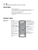
Watlow MicroDIN Quick Start Guide Troubleshooting Alarms and Errors most likely problems are listed first Indication Symptoms • No power. Error = off (Normal = steady green) • Unit will not communicate. Error = off (Normal = pulsing green) • Input is in error condition. Error = steady red (Normal = off ) • Alarm won’t occur. Alarm = steady red • Alarm won’t clear.
Watlow MicroDIN Quick Start Guide Corrective Action • Check switches, fuses, breakers, interlocks, limits, connectors, etc.
Watlow MicroDIN Quick Start Guide Specifications: (2346) Control Mode • Microprocessor-based, user selectable control modes • Single input, single output • Heat or cool auto-tuning Output #1: User selectable • ON/OFF; P, PI, PD, PID heat or cool action adjustable switching differential: 1 to 9999 or 0.1 to 999.9°F or °C • Proportional band: 0 to 9999, or 0.0 to 999.9°F or °C • Integral: 0.00 to 99.99 minutes per repeat • Reset: 0.00 to 99.99 repeats per minute • Derivative/Rate: 0.00 to 9.
Watlow MicroDIN Quick Start Guide Primary Control Output (heating or cooling) • Output update rate: 10 per second, 10Hz (maximum) Internal Load Switching (nominal): Switched dc (isolated) signal, 22 to 28VÎ (Vdc), current limited @ 30mA Overload current and short circuit protection External Load Switching (maximum): • Open Collector 42VÎ (Vdc) @ 1A Alarm Output • Output update rate 2 per second (2Hz) • Electromechanical relay, Form A, 2A @ 30VÎ (Vdc) or 240VÅ(Vac), • Alarm output can be latching or no
Watlow MicroDIN Quick Start Guide Ordering Information (2347) To order, complete the code number to the right with the information below: UD1A-1CES-__00 MicroDIN Controller DIN Rail Mount Temperature Controller with no operator interface and EIA-485 Modbus™ RTU Serial Communications. Hardware 1A = Single channel, low voltage Input 1 = Type B, C, D, E, J, K, N, PT2, R, S, T, 1°RTD, 0, 1°RTD (JIS and DIN) Control Output C = Switched (DC), logic signal, isolated.
Watlow MicroDIN Quick Start Guide How to Reach Us Technical Assistance If you encounter a problem with your Watlow controller, review your configuration information to verify that your selections are consistent with your application: inputs, outputs, alarms, limits, etc. If the problem persists after checking the configuration of the controller, you can get technical assistance from your local Watlow representative, or by dialing +1 (507) 494-5656 between 7 a.m. and 5 p.m., Central Standard Time (CST).