EZ-ZONE® RUI/Gateway User’s Guide EZ-ZONE RM EZ-ZONE ST RUI/Gateway TOTAL CUSTOMER SATISFACTION 3 Year Warranty ISO 9001 1241 Bundy Boulevard., Winona, Minnesota USA 55987 Phone: +1 (507) 454-5300, Fax: +1 (507) 452-4507 http://www.watlow.com 0600-0060-0000 Rev. C March 2012 Registered Company Winona, Minnesota USA Made in the U.S.A.
Safety Information Unit is compliant with European Union directives. See Declaration of Conformity for further details on Directives and Standards used for Compliance. We use note, caution and warning symbols throughout this book to draw your attention to important operational and safety information. A “NOTE” marks a short message to alert you to an important detail. Unit has been reviewed and approved by CSA International for use as Temperature IndicatingRegulating Equipment per CSA C22.2 No. 24 or C22.
• Your P.O. number • Detailed description of the problem • Any special instructions • Name and phone number of person returning the product. 2. Prior approval and an RMA number from the Customer Service Department is required when returning any product for credit, repair or evaluation. Make sure the RMA number is on the outside of the carton and on all paperwork returned. Ship on a Freight Prepaid basis. 3. After we receive your return, we will examine it and try to verify the reason for returning it. 4.
TC Table of Contents Chapter 1: Overview . . . . . . . . . . . . . . . . . . . . . . . . . . . . . . . . . . . . . 3 Features and Benefits. . . . . . . . . . . . . . . . . . . . . . . . . . . . . . . . . . . . . . . . 3 RUI/GTW Panel Cutout Dimensions. . . . . . . . . . . . . . . . . . . . . . . . . . . . . 4 Chapter 2: Install, Wire and Set Address . . . . . . . . . . . . . . . . . . .
TC Table of Contents (cont.) Chapter 5: Using an RUI/Gateway. . . . . . . . . . . . . . . . . . . . . . . . . . . 29 Conceptual View of the RUI/GTW. . . . . . . . . . . . . . . . . . . . . . . . . . . . . . 29 Using RUI Lockout and Password Security. . . . . . . . . . . . . . . . . . . . . . 29 Using Lockout Method 1 (Read and Set Lock). . . . . . . . . . . . . . . . . . 29 Using Lockout Method 2 (Password Enable).
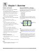
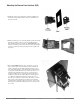
1 Chapter 1: Overview Features and Benefits Using the RUI/GTW as a Gateway Remote User Interface/Gateway (RUI/GTW) • Uses one RUI for multiple zones The addition of a gateway card allows information to be passed from the Standard Bus side of the gateway (EZ-ZONE®-family controllers) to one or more of the following popular field bus networks: • The RUI without a gateway card utilizes minimal panel depth allowing it to fit in small spaces • EtherNet/IP™ • DeviceNet™ • Modbus TCP • Modbus RTU • Profibus
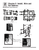
2 Chapter 2: Install, Wire and Set Address RUI/GTW Panel Cutout Dimensions 44.96 to 45.47 mm (1.77 to 1.79 inches) 15.8 mm (0.62 in) 101.6 mm (4.00 in) 53.3 mm (2.10 in) 44.96 to 45.47 mm (1.77 to 1.79 inches) 53.3 mm (2.10 in) Side panel thickness 1.53 to 9.52 mm (0.060 to 0.375) Front E8 51.2 mm (2.02 in) 21.6 mm (0.85 in) Minimum 98 E7 99 E6 CF E5 CD E4 CE E3 E2 E1 Top Back Top View long case (EZK_-_(2, 3, 5 or 6)_ _-_ _ _ _) 21.6 mm (0.85 in) Minimum 76.25 mm (3.00 in) 15.
Mounting the Remote User Interface (RUI) 1. Make the panel cutout using the mounting template dimensions in this chapter. Insert the case assembly into the panel cutout. 2. While pressing the case assembly firmly against the panel, slide the mounting collar over the back of the RUI. If the installation does not require an IP66/NEMA 4X seal, slide the mounting collar up to the back of the panel tight enough to eliminate the spacing between the gasket and the panel. 3.
Ó Warning: Use National Electric (NEC) or other country-specific standard wiring and safety practices when wiring and connecting this controller to a power source and to electrical sensors or peripheral devices. Failure to do so may result in damage to equipment and property, and/or injury or loss of life. Power Slot C long case 98 99 power power • Minimum/Maximum Ratings fuse • 85 to 264VÅ (ac) Slot C short case CF CD 98 CE 99 B5 CF D6 CD D5 CE • 20.4 to 26.
Ó Warning: Use National Electric (NEC) or other countryspecific standard wiring and safety practices when wiring and connecting this controller to a power source and to electrical sensors or peripheral devices. Failure to do so may result in damage to equipment and property, and/or injury or loss of life.
Ó Warning: Use National Electric (NEC) or other country-specific standard wiring and safety practices when wiring and connecting this controller to a power source and to electrical sensors or peripheral devices. Failure to do so may result in damage to equipment and property, and/or injury or loss of life. Wiring a Serial EIA-485 Network Note: The RUI without a gateway installed, can communicate using Watlows' Standard Bus only. Do not route network wires with power wires.
Ó A network using Watlow's Standard Bus and an RUI Power Supply EZ-ZONE ST ST_ _ - _ _ A _ -_ _ _ _ fuse EZ-ZONE RMC RMC _ _ _ _ _ _ _ _ _ A _ _ 98 99 CF CD B5 D6 CE D5 T+ / R+ T- / R- Warning: Use National Electric (NEC) or other countryspecific standard wiring and safety practices when wiring and connecting this controller to a power source and to electrical sensors or peripheral devices. Failure to do so may result in damage to equipment and property, and/or injury or loss of life.
3 Chapter 3: Keys and Displays Upper Display: In the Home Page, displays the parameter specified by Custom 1 in the factory page, otherwise displays the value of the parameter in the lower display. Temperature Units: ® Output Activity: Zone Display: Number LEDs indicate activity of outputs. A flashing light indicates output activity. Indicates the controller zone that the RUI is currently communicating with.
Display [Attn] Parameter Name Description Attention An active message will cause the display to toggle between the normal settings and the active message instance in the upper display, [Attn] in the lower display, and the Zone will flash reflecting the Zone which generated the message. Your response will depend on the message and the controller settings. Some messages, such as Ramping and Tuning, indicate that a process is underway.
Changing the Position of a Controllers Operations Page and or Profiling Page in the Lockout Menu Example 3 The operator wants to read the Operations Page, Setup Page. Profiling Page, Diagnostics Menu, Lock Menu, Calibration Menu and Custom Menus. The operator also wants to read and write to the Home Page.
Programming the EZ Key Using an RUI 2. Press the Up ¿ or Down ¯ key until the Action prompt [`ACt] appears in the upper display and [`SEt] will appear in the lower display. The following examples show how to program the EZ Key to start and stop a profile using PM, RM and ST family controllers. 3. Press the Advance Key ‰ once and select the Action instance (1-8) using the Up ¿ or Down ¯ key. Upon entry, the upper display will show [```1] and the lower display will show [`ACt].
Note: As of this firmware revision (8.0), two instances appear to be available and selectable. However, instance 2 is provided for future firmware enhancements only. 4. Press the Advance Key ‰ once and then using the Up ¿ or Down ¯ key to select Profile Start/Stop [p;sts] as the Function [``Fn]. 5. Press the Advance Key ‰ once and then using the Up ¿ or Down ¯ key select the Function Instance [``F;i] (Function Instance equals Profile 1, 2, 3 or 4). 5.
Default Home Pages As stated above, the user can define pairs of prompts to appear on the display every time the Advance ‰ key is pushed. For each controller the first pair will always be as defined in the Custom Menu and as stated will default (factory settings) to the Active Process Value loop 1 [aC;pu], and the Active Set Point loop 1 [aC;sp]. For the Limit, it would be the Active Process Value [aC;pu],and Limit Status, either Safe [safe] or Fail [fail].
EZ-ZONE PM Express Home Page Custom Menu Number Home Page Display (defaults) Parameter Name Custom Menu Display (defaults) Parameter Page and Menu IF 4th digit of PN is equal to: PM _ [L] _ _ _ - _ _ _ _ B _ _ (Limit Controller) 1 Upper or left display 2 Lower or right display (value only) [safe] or [fail[ Active Process Value Home Page [AC;Pu] Limit State Home Page [`l;st] ---- (value only) Limit Low Set Point [`ll;s] ---- (value only) Limit High Set Point [`lh;s] ---- (value only) Al
EZ-ZONE ST Home Page Home Custom Page Menu Display Number (defaults) Parameter Name 1 Upper Display (value only) Active Process Value 2 Lower Display (value only) *Active Set Point Custom Menu Display (defaults) Parameter Page and Menu [AC;Pu] Operations Page, Analog Input Menu [AC;SP] Operations Page, Monitor Menu IF 4th digit of PN is equal to: ST _ [L] - _ _ _ _ - _ _ _ _ (Integrated Limit included) (value only) 3 4 [l;st] Process Value Analog Input 2 [`pro] Operations Page, Analog Inp
EZ-ZONE PM Home Page Custom Menu Number Home Page Display Home Page Defaults Custom Menu Display (defaults) Parameter Page and Menu All Models 1 Numerical value 2 Numerical Active Set Point (1)* value Active Process Value (1) [AC;Pu] Operations Page, Monitor Menu [AC;SP] Operations Page, Monitor Menu IF 10th digit of PN is equal to: PM _ _ _ _ _ - _ [L, M] _ _ _ _ _ 3 Numerical value 4 [safe] or [fail] Process Value (2) [AC;Pu] Operations Page, Monitor Menu Limit Status [AC;SP] Home P
EZ-ZONE RMC (Controller) Home Page Custom Menu Number Home Page Display Parameter Name Custom Menu Display 1 Upper Display Numerical value Active Process Value [Ac;Pu] Operations Page, Analog Input Menu 2 Lower Display Numerical value Active Set Point [Ac;SP] Operations Page, Monitor Menu 3 [C;;M1] Control Mode [`C;M] Operations Page, Loop Menu 4 [h;Pr1] Heat Power [`h;Pr] Operations Page, Monitor Menu 5 [C;Pr1] Cool Power* [`C;Pr] Operations Page, Monitor Menu 6 [AUt1] Autotu
EZ-ZONE RMH (High Density) Home Page Custom Menu Number Home Page Display Parameter Name Custom Menu Display 1 Upper Display Numerical value Active Process Value 1 [Ac;Pu] Operations Page, Analog Input Menu 2 Lower Display Numerical value Active Set Point 1 [Ac;SP] Operations Page, Monitor Menu 3 [C;;M1] Control Mode [`C;M] Operations Page, Loop Menu 4 to 48 49 to 50 Parameter Page and Menu Same as above instance 4 - 16 (skipped) None [nonE] (Add parameters to the Home Page in the Cu
4 Chapter 4: RUI Page The RUI Page • Press the Advance Key ‰ to move through the parameters of the menu. • Press the Up ¿ or Down ¯ key to move through the parameter values. • Press the Infinity Key ˆ to move backwards through the levels: parameter to menu; menu to Home Page. • Press and hold the Infinity Key ˆ for two seconds to return to the Home Page. To go to the RUI Page from the Home Page, press both the Down ¯ and Advance ‰ keys for three seconds.
Display Parameter name Description Range Default Modbus Relative Address CIP Class Instance Attribute hex (dec) Profibus Index Parameter ID Data Type & Read/ Write [CoM] (instance 2 appears if PN is equal to: EZK _-_ [2, 3, 5 or 6] _ _-A _ AA) [`rUi] Communications Menu [`Ad;s] [ Ad.S] Communications 1 RUI Address Set the Standard Bus address of this RUI. Each RUI on the network must have a unique address. 1 to 8 1 410 0x96 (150) 1 1 ---- 17001 uint RWE [St;2n] [St.
Display Parameter name Description Range Default Modbus Relative Address CIP Class Instance Attribute hex (dec) Profibus Index Parameter ID Data Type & Read/ Write [iP;F2] [ip.F2] Communications 2 IP Fixed Address Part 2 Set the IP address of this gateway. Each device on the network must have a unique address. 0 to 255 254 ---- ---- ---- 17045 uint RW [iP;F3] [ip.F3] Communications 2 IP Fixed Address Part 3 Set the IP address of this gateway.
Display Parameter name Description Range Default Modbus Relative Address CIP Class Instance Attribute hex (dec) Profibus Index Parameter ID Data Type & Read/ Write [iP;g2] [ip.g2] Communications 2 IP Fixed Gateway Part 2 Set the router IP address for the remote network. 0 to 255 0 ---- ---- ---- 17027 uint RW [iP;g3] [ip.g3] Communications 2 IP Fixed Gateway Part 3 Set the router IP address for the remote network. 0 to 255 0 ---- ---- ---- 17028 uint RW [iP;g4] [ip.
Parameter name Description Display Range Modbus Relative Address Default CIP Class Instance Attribute hex (dec) Profibus Index Parameter ID Data Type & Read/ Write [glbl] [`rUi] Global Menu [[C;led] Global Menu [C.LEd] Communications LED Action Turns comms LED on or off for selected comms ports. [Con1] Comm port 1 [Con2] Comm port 2 [both] Comm port 1 and 2 [`off] Off Both 386 0x67 (103) 1 0x0E (14) ---- 3014 uint RWES ---- 0x67 (103) 1 0x1D (29) ---- 3029 uint RWES [`d;ti] [ d.
Display [`s;of] [ So.F] Parameter name Description Gateway (1 to 16) Profibus DP Slot Offset Set Profibus instance member offset for this Standard Bus controller address.
Display Parameter name Description Range Default Modbus Relative Address CIP Class Instance Attribute hex (dec) Profibus Index Parameter ID Data Type & Read/ Write [ULoC] [`rui] Unlock Security Setting Menu [Code] [CodE] Security Setting Public Key If Rolling Password turned on, generates a random number when power is cycled. If Rolling Password is off fixed number will be displayed.
Display Parameter name Description Range Default Modbus Relative Address CIP Class Instance Attribute hex (dec) Profibus Index Parameter ID Data Type & Read/ Write [iP;A4] [iP.A4] Diagnostics Menu IP Actual Address Part 4 View or change the fourth part of this controller's IP address. 0 to 255 None ---- ---- ---- 17017 uint R [iP;A5] [iP.A5] Diagnostics Menu IP Actual Address Part 5 View or change the fourth part of this controller's IP address.
5 Chapter 5: Using an RUI/Gateway Conceptual View of the RUI/GTW modified by anyone who knows how to find their way to the [SLoC] and [rloC] parameters. As shown in the following network screen shots the gateway allows for connectivity between dissimilar networks. Within the Watlow controllers there are many parameters (members), of which, some can be read and some read and or written to. As an example, the Process Value can be read only, where the Closed Loop Set Point can be read and or written to.
Note: Using Method 1 Lockout all settings can be modified by anyone who knows how to find their way to the [SLoC] and [rloC] parameters need to know what those passwords are to acquire a higher level of access to the control. Back out of this menu by pushing the Infinity ˆ key. Once out of the menu, the Password Security will be enabled. Method 2- Enable Password Security [pas;e] and then modify the Lock Level [loC;l] value which ranges from 1 to 5.
Differences Between a User Without Password, User With Password and Administrator you’ll notice that the Modbus register that holds the Closed Loop Set Point value is 2160; if using Map2 then the address would be 2640. To read instance one Closed Loop Set Point from Standard Bus address 1 the appropriate absolute Modbus address would be: 2160 + 400001 + Modbus offset (0) = 402161. - User without a password is restricted by the Locked Access Level [loC;l].
Assembly Definition Addresses - Fixed addresses used to define the parameter that will be stored in the "Working Addresses", which may also be referred to as a pointer. The value stored in these addresses will reflect (point to) the Modbus address of a parameter within the controller. Memory Blocks" found in the appendix of this Users Guide reflects the assemblies and their associated addresses. To learn more about the Modbus RTU protocol point your browser address below: http://www.modbus.
using CIP can be accomplished via explicit and or implicit communications. Explicit communications usually requires the use of a message instruction within the Programmable Logic Controller (PLC) but there are other ways to do this as well. Implicit communications is also commonly referred to as polled communications.
ing information in the message instruction: Class = 104 or (0x68) Instance = 1 Attribute = 1 the first 5 members of the assembly and this information would then be passed implicitly to the Master on the DeviceNet™ network. The EDS (Electronic Data Sheet) can be found on the CD shipped with the product "Controller Support Tools". Note that the instance is identified as instance 1 because there is no offset to add.
Note that the instance is identified as instance 1 because there is no offset to add. RUI prompt entry for gateway instance 1 follows: Module Status (MS) cont. Indicator LED Description Flashing Red Major Recoverable Fault. Red Major Unrecoverable Fault. Green The device is operating normally. [`oSt] = 0 RUI prompt entry for gateway instance 2 (PM2) follows: [`oSt] = 4 To learn more about CIP and DeviceNet point your browser to: http://www.odva.
outputs from the Master and is used exclusively when communicating implicitly. For any given RUI gateway instance (EZ-ZONE controller), the input assembly size will never be greater than 20, 32-bit members. The user entry ranges from 0 to 20. Map 2 Modbus registers. When found, notice that the relative Modbus register is 2160 (Map 1) or 2640 (Map 2). To read the set point from address 1 the appropriate absolute Modbus address would be: 2160 + 400001 + Modbus offset (0) = 402161.
Network Status Indicator State Steady Off Flashing Green Steady Green Flashing Red Steady Red Flashing Green / Red Summary Module Status (cont.) Requirement Not powered, no IP address If the device does not have an IP address (or is powered off), the network status indicator shall be steady off. No connections If the device has no established connections, but has obtained an IP address, the network status indicator shall be flashing green.
As with all of the other available protocols prior to establishing communications between Master and the slave the gateway instance must first be enabled Slot Offset = 61 Index = 0 Profibus Slot Offset 0 Profibus Slot Offset 20 [gtW] 1 = PM1 [Com] Instance 2 [Com] Instance 1 Profibus Slot Offset 40 Profibus Address [p;add] = 0 - 126 Standard Bus Address [Ad;S] = 1-8 Address Lock [a;loc] = [yes] or [no] Start Node to Scan [St;2n] = 1-24 Profibus Slot Offset 60 [gtW] 4 = PM4 RUI/Gateway Setup P
Software Configuration Using EZ-ZONE® Configurator Software To enable a user to configure the RUI/GTW using a personal computer (PC), Watlow has provided free software for your use. If you have not yet obtained a copy of this software insert the DVD that came with the product (Controller Support Tools) into your CD/ DVD drive and install the software.
The menu structure as laid out within this software follows: - Communications - Global - Local Remote Gateway - Lock - Diagnostics In the screen shot above the RUI/GTW is shown highlighted to bring greater clarity to the subject in focus. Any EZ-ZONE device on the network will appear in this window and would be available for the purpose of configuration and monitoring. After clicking on the RUI/GTW simply click the next button once again where the screen below will appear.
Although the RUI/GTW now contains the configuration (because this entire discussion focused on doing the configuration on-line) it is suggested that after the configuration process is completed that the user save this file to the PC for future use. If for some reason someone inadvertently changed a setting without understanding the impact, it would be easy and perhaps faster to download a saved configuration back to the RUI/GTW versus trying to figure out what was changed.
Saving Settings to Non-volatile Memory When save to EEPROM is enabled, values are saved once every five seconds if a value written has changed. if the EEPROM is disabled, any changes from the keypad that cause a change in the controller will initiate a save of all values. If controller settings are entered from the front panel (PM) or via an RUI, changes are always saved to non-volatile memory (EEPROM) in the controller (RM, PM or ST).
6 Chapter 6: Appendix Troubleshooting Indication No Display Description Possible Cause(s) No display indication or LED illumination • Power to RUI (Remote User Interface) is off • Fuse open • Breaker tripped • Safety interlock switch open • Separate system limit controller activated • Wiring error • Incorrect voltage to controller • Turn on power. • Keypad malfunction • Replace or repair the RUI.
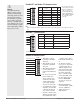
Modbus - Programmable Memory Blocks PM Modbus Assembly Definition Assembly Definition Addresses 40 & 41 42 & 43 44 & 45 46 & 47 48 & 49 50 & 51 52 & 53 54 & 55 56 & 57 58 & 59 60 & 61 62 & 63 64 & 65 66 & 67 68 & 69 70 & 71 72 & 73 74 & 75 76 & 77 78 & 79 Assembly Working Addresses 200 & 201 202 & 203 204 & 205 206 & 207 208 & 209 210 & 211 212 & 213 214 & 215 216 & 217 218 & 219 220 & 221 222 & 223 224 & 225 226 & 227 228 & 229 230 & 231 232 & 233 234 & 235 236 & 237 238 & 239 Assembly Definition Address
PM Modbus Default Assembly Structure 80-119 Assembly Definition Addresses Default Pointers Assembly Working Addresses Assembly Definition Registers Default Pointers Assembly Working Registers Registers 80 & 81 Registers 240 & 241 Registers 100 & 101 Registers 260 & 261 Pointer 21 = 360 & 361 Analog Input 1 Process Value Registers 82 & 83 Pointer 35 = 2520 & 2521 Profile Start Value of Pointer 25 Registers 110 & 111 Registers 250 & 251 Pointer 36 = 2540 & 2541 Profile Action Request Value of Po
RM Modbus Assembly Definition Assembly Definition Address and Assembly Working Addresses Definition Addresses Working Addresses Definition Addresses Working Addresses 40 & 41 200 & 201 120 & 121 280 & 281 42 & 43 202 & 203 122 & 123 282 & 283 44 & 45 204 & 205 124 & 125 284 & 285 46 & 47 206 & 207 126 & 127 286 & 287 48 & 49 208 & 209 128 & 129 288 & 289 50 & 51 210 & 211 130 & 131 290 & 291 52 & 53 212 & 213 132 & 133 292 & 293 54 & 55 214 & 215 134 & 135 294 & 295 56 & 57
RM Modbus Default Assembly Structure 40-119 Assembly Definition Addresses Default Pointers Assembly Working Addresses Assembly Definition Addresses Default Pointers Assembly Working Addresses Registers 40 & 41 Registers 200 & 201 Registers 80 & 81 Registers 240 & 241 Pointer 1 = 0 & 1 Closed Loop Set Point 1 Registers 42 & 43 Pointer 2 = 0 & 1 Closed Loop Set Point 2 Registers 44 & 45 Pointer 3 = 0 & 1 Closed Loop Set Point 3 Registers 46 & 47 Pointer 4 = 0 & 1 Closed Loop Set Point 4 Registers
RM Modbus Default Assembly Structure 120 - 199 Assembly Definition Registers Default Pointers Assembly Working Registers Assembly Definition Registers Default Pointers Assembly Working Registers Registers 120 & 121 Registers 280 & 281 Registers 160 & 161 Registers 320 & 321 Pointer 41 = 0 & 1 Undefined Registers 122 & 123 Pointer 42 = 0 & 1 Undefined Registers 124 & 125 Pointer 43 = 0 & 1 Undefined Registers 126 & 127 Pointer 44 = 0 & 1 Undefined Registers 128 & 129 Pointer 45 = 0 & 1 Undefi
CIP Implicit Assemblies ST CIP Implicit Assemblies CIP Implicit Assembly Originator (Master) to Target (ST) Parameter Class, Instance, Attritbute Assembly Members Assembly Class, Instance, Attritbute ST Data Type 1 0x77, 0x01, 0x01 DINT Control Loop 1, User Control Mode 0x97, 0x01, 0x01 DINT 2 3 4 5 6 7 8 9 10 11 12 13 14 15 16 17 18 19 20 0x77, 0x01, 0x02 0x77, 0x01, 0x03 0x77, 0x01, 0x04 0x77, 0x01, 0x05 0x77, 0x01, 0x06 0x77, 0x01, 0x07 0x77, 0x01, 0x08 0x77, 0x01, 0x09 0x77, 0x01, 0x0A 0x77,
PM CIP Implicit Assemblies CIP Implicit Assembly Originator (Master) to Target (PM) Assembly Members Assembly Class, Instance, Attritbute PM Data Type 1 0x77, 0x01, 0x01 DINT 2 3 4 5 6 7 8 9 10 11 12 13 14 15 16 17 18 19 20 0x77, 0x01, 0x02 0x77, 0x01, 0x03 0x77, 0x01, 0x04 0x77, 0x01, 0x05 0x77, 0x01, 0x06 0x77, 0x01, 0x07 0x77, 0x01, 0x08 0x77, 0x01, 0x09 0x77, 0x01, 0x0A 0x77, 0x01, 0x0B 0x77, 0x01, 0x0C 0x77, 0x01, 0x0D 0x77, 0x01, 0x0E 0x77, 0x01, 0x0F 0x77, 0x01, 0x10 0x77, 0x01, 0x11 0x77, 0x0
RME CIP Implicit Assemblies CIP Implicit Assembly Originator (Master) to Target (RME) Assembly Members Assembly Class, Instance, Attritbute RM Module Data Type Parameter Parameter Class, Instance, Attritbute PLC Data Type 1 2 3 4 5 6 7 8 9 10 11 12 13 14 15 16 17 18 19 20 0x77, 0x01, 0x01 0x77, 0x01, 0x02 0x77, 0x01, 0x03 0x77, 0x01, 0x04 0x77, 0x01, 0x05 0x77, 0x01, 0x06 0x77, 0x01, 0x07 0x77, 0x01, 0x08 0x77, 0x01, 0x09 0x77, 0x01, 0x0A 0x77, 0x01, 0x0B 0x77, 0x01, 0x0C 0x77, 0x01, 0x0D 0x77, 0x01,
RMC CIP Implicit Assemblies RMC CIP O to T Implicit Assemblies CIP Implicit Assembly Originator (Master) to Target (RMC) Assembly Members Assembly Class, Instance, Attritbute RM Module Data Type 1 2 3 4 5 6 7 8 9 10 11 12 13 14 15 16 17 18 19 20 21 22 23 24 25 26 27 28 29 30 31 32 33 34 35 36 37 38 39 40 0x77, 0x01, 0x01 0x77, 0x01, 0x02 0x77, 0x01, 0x03 0x77, 0x01, 0x04 0x77, 0x01, 0x05 0x77, 0x01, 0x06 0x77, 0x01, 0x07 0x77, 0x01, 0x08 0x77, 0x01, 0x09 0x77, 0x01, 0x0A 0x77, 0x01, 0x0B 0x77, 0x01, 0x0
RMC CIP T to O Implicit Assemblies CIP Implicit Assembly Target (RMC) to Originator (Master) Assembly Members 0 1 2 3 4 5 6 7 8 9 10 11 12 13 14 15 16 17 18 19 20 21 22 23 24 25 26 27 28 29 30 31 32 33 34 35 36 37 38 39 40 Assembly Class, Instance, Attritbute Cannot be changed 0x77, 0x02, 0x01 0x77, 0x02, 0x02 0x77, 0x02, 0x03 0x77, 0x02, 0x04 0x77, 0x02, 0x05 0x77, 0x02, 0x06 0x77, 0x02, 0x07 0x77, 0x02, 0x08 0x77, 0x02, 0x09 0x77, 0x02, 0x0A 0x77, 0x02, 0x0B 0x77, 0x02, 0x0C 0x77, 0x02, 0x0D 0x77, 0x02,
RMH, RMS and RML CIP Implicit Assemblies RMH, RMS and RML O to T CIP Implicit Assemblies CIP Implicit Assembly Originator (Master) to Target (RMH / RMS / RML) Assembly Members Assembly Class, Instance, Attritbute RM Module Data Type Parameter Parameter Class, Instance, Attritbute PLC Data Type 1 2 3 4 5 6 7 8 9 10 11 12 13 14 15 16 17 18 19 20 21 22 23 24 25 26 27 28 29 30 31 32 33 34 35 36 37 38 39 40 0x77, 0x01, 0x01 0x77, 0x01, 0x02 0x77, 0x01, 0x03 0x77, 0x01, 0x04 0x77, 0x01, 0x05 0x77, 0x01, 0x
RMH, RMS and RML T to O CIP Implicit Assemblies CIP Implicit Assembly Target (RMH / RMS / RML) to Originator (Master) Assembly Members Assembly Class, Instance, Attritbute RM Module Data Type Parameter Parameter Class, Instance, Attritbute PLC Data Type 0 1 2 3 4 5 6 7 8 9 10 11 12 13 14 15 16 17 18 19 20 21 22 23 24 25 26 27 28 29 30 31 32 33 34 35 36 37 38 39 40 Cannot be changed 0x77, 0x02, 0x01 0x77, 0x02, 0x02 0x77, 0x02, 0x03 0x77, 0x02, 0x04 0x77, 0x02, 0x05 0x77, 0x02, 0x06 0x77, 0x02, 0x07 0
Specifications Basic Remote User Interface (RUI) Operator Interface • Dual 4-digit, 7-segment LED displays • Forward, backward, up and down keys plus a customer programmable function key • Typical display update rate 1Hz • Agency approved to IP65/NEMA 4X (indoor use only) • Standard Bus protocol ships with all units • Optional Communications Protocols: - EIA 232/485 Modbus RTU - EtherNet/IP and Modbus TCP - DeviceNet - Profibus DP Line Voltage/Power • 85 to 264VÅ (ac), 47 to 63Hz, 10VA maximum • 20 to 28Vı
Ordering Information EZ-ZONE® Remote Users Interface E Z K __ - __ __ __ __ - __ __ __ __ Remote User Interface (RUI) B Basic 1⁄16 DIN Power Supply Voltage for Remote User Interface (RUI) L H Low voltage 24 to 28V‡ (ac/dc) Universal high voltage 100 to 240V‡ (ac/dc) Communications Options (Standard Bus always included) A 2 3 5 6 None (short case) EIA 232/485 Modbus® RTU (long case) EtherNet/IP™ Modbus TCP (long case) DeviceNet™ (long case) Profibus DP (long case) Custom Remote User Interface (RU
Declaration of Conformity Series EZ-ZONE® RUI WATLOW an ISO 9001 approved facility since 1996. 1241 Bundy Blvd. Winona, MN 55987 USA Declares that the following product: ® Series EZ-ZONE RUI Designation: Model Numbers: EZK (A, B, C, D or E) (A, L or H) (any three numbers or letters) A, A, (any two letters or numbers) Classification: Temperature control, Installation Category II, Pollution degree 2 IP66 Environmental seal on front panel.
How to Reach Us Corporate Headquarters Watlow Electric Manufacturing Company 12001 Lackland Road St. Louis, MO 63146 Sales: 1-800-WATLOW2 Manufacturing Support: 1-800-4WATLOW Email: info@watlow.com Website: www.watlow.com From outside the USA and Canada: Tel: +1 (314) 878-4600 Fax: +1 (314) 878-6814 Latin America Watlow de México S.A. de C.V. Av. Fundición No. 5 Col. Parques Industriales Querétaro, Qro. CP-76130 Mexico Tel: +52 442 217-6235 Fax: +52 442 217-6403 Europe Watlow France Tour d'Asnières.