EZ-ZONE® RM High Density Module User’s Guide RM High Density Module TOTAL CUSTOMER SATISFACTION 3 Year Warranty ISO 9001 Registered Company 1241 Bundy Boulevard., Winona, Minnesota USA 55987 Phone: +1 (507) 454-5300, Fax: +1 (507) 452-4507 http://www.watlow.com 0600-0074-0000 Rev. E December 2013 Winona, Minnesota USA Made in the U.S.A.
Safety Information Unit is compliant with European Union directives. See Declaration of Conformity for further details on Directives and Standards used for Compliance. We use note, caution and warning symbols throughout this book to draw your attention to important operational and safety information. A “NOTE” marks a short message to alert you to an important detail. Unit has been reviewed and approved by Factory Mutual as a Temperature Limit Device per FM Class 3545 standard. See: www. fmglobal.
returning any product for credit, repair or evaluation. Make sure the Return Merchandise Authorization number is on the outside of the carton and on all paperwork returned. Ship on a Freight Prepaid basis. 3. After we receive your return, we will examine it and try to verify the reason for returning it. 4. In cases of manufacturing defect, we will enter a repair order, replacement order or issue credit for material returned.
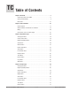
TC Table of Contents Chapter 1: Overview . . . . . . . . . . . . . . . . . . . . . . . . . . . . . . . . . . . . . 3 A Conceptual View of the RMH. . . . . . . . . . . . . . . . . . . . . . . . . . . . . . . . 6 Getting Started Quickly. . . . . . . . . . . . . . . . . . . . . . . . . . . . . . . . . . . . . . . 9 Dimensions. . . . . . . . . . . . . . . . . . . . . . . . . . . . . . . . . . . . . . . . . . . . . . . 15 Chapter 2: Install and Wire. . . . . . . . . .
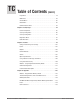
TC Table of Contents (cont.) Logic Menu. . . . . . . . . . . . . . . . . . . . . . . . . . . . . . . . . . . . . . . . . . . . . . . 79 Math Menu. . . . . . . . . . . . . . . . . . . . . . . . . . . . . . . . . . . . . . . . . . . . . . . 88 Variable Menu. . . . . . . . . . . . . . . . . . . . . . . . . . . . . . . . . . . . . . . . . . . . . 92 Global Menu. . . . . . . . . . . . . . . . . . . . . . . . . . . . . . . . . . . . . . . . . . . . . . 92 Communications Menu. . . . . . . . . . . . . . . . . . .
1 Chapter 1: Overview Available EZ-ZONE RM System Literature and Resources Document Title and Part Number Description EZ-ZONE Rail Mount Access (RMA) User's Guide, part number: 0600-0072-0000 Describes how to connect the RM system into an industrial network, how to use data logging, module backup and the real-time clock. EZ-ZONE Rail Mount Controller (RMC) User's Guide, part number: 0600-0070-0000 The RMC module is an advanced integrated controller capable of PID and limit control.
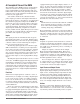
Introduction • Users can easily tell that the entire thermal system is functioning properly The EZ-ZONE ® RM High Density (RMH) control module provides multi-loop (4 to 16 loops) PID control in a small footprint. The RMH takes the pain out of solving your thermal loop requirements as a standalone module or in applications that require distributed control. It just got a whole lot easier to solve the thermal requirements of your system.
Control capability • Allows individual modules to be mounted closer to the physical input and output devices to which they are wired • Improves system reliability and lowers wiring costs Agency Approvals: UL ® listed, CE, RoHS, W.E.E.E. SEMI F47-0200, Class 1 Div.
A Conceptual View of the RMH The flexibility of the RMH’s software and hardware allows for variation in configurations. Acquiring a better understanding of its functionality and capabilities while at the same time planning out how the controller can be used will deliver maximum effectiveness in your application. It is useful to think of the controller in three parts: inputs, procedures and outputs. Information flows from an input to a procedure to an output when the controller is properly configured.
dard Bus to successfully communicate; disconnect all Modbus devices from the network. Once done using the RUI or EZ-ZONE Configurator software, switch the protocol back to Modbus RTU and reconnect all Modbus devices to re-establish communications over Modbus. A Conceptual View of RM Hardware Configurations Due to the scalability and flexibility in the RM system a user has several options available in the way that the hardware can be connected. Listed below are a few examples.
RMH Controller RM Access Slot C Slot C Slot C Slot E RMC Controller Power Supply RMC Controller RMH Controller Slot C Slot C OIT Module Orientation The picture that follows represents one of several different RM modules. All of them will have four slots on the face (slot A, B, D, and E) and one on the bottom (slot C) not shown. All of these slots are not always used on all modules. On the face of the module there is a button (yellow circle) under the Zone address ([5]).
Getting Started Quickly Consider taking the following steps to quickly commission your control: • Wire and connect the power source to the control • Wire and connect input and output devices to the control • Power up the control and navigate to the Setup Page to configure inputs, outputs, alarms, etc... • Once the control is setup, navigate to the Operations Page to modify set points.
EZ-ZONE RMH Module - System Diagram 16 Control Loops - Slots A, B, D and E R M H x - [1,2] [1,2] [1,2] [1,2] - A A A A Input Function Input Sensor Output Function Analog Input 1 through 16 None, Thermocouple, 2-Wire RTD (100, 1k), Thermistor (5k, 10K, 20k, 40k), Process (V, mV, mA) or 1K Potentiometer PID Controller Slot A, B, D, E Zone and Status LED RUI, PC, PLC or HMI EIA - 485 Communications Standard Bus (optional Modbus RTU) Modbus RTU Address 1 - 16 Indicates Zone Address Zone Selection Stan
EZ-ZONE RMH Module - System Diagram 8 Control Loops - Slots A, B 4 - Form A Mechanical Relays - Slot D 6 - Digital I/O - Slot E R M H x - [1,2] [1,2] J C - A A A A Input Function Input Sensor Output Function Analog Input 1 through 8 None, Thermocouple, 2-Wire RTD (100, 1k), Thermistor (5k, 10K, 20k, 40k), Process (V, mV, mA) or 1K Potentiometer PID Controller Slot A, B 4 - Mechanical Relay Outputs Form A Analog Input Alarm Cool Power Heat Power Compare Counter Digital I/O Profile Event Output A-H Functi
EZ-ZONE RMH Module - System Diagram 8 Control Loops - Slots A, B 6 - Digital I/O - Slot D 4 - Form A Mechanical Relays - Slot E R M H x - [1,2] [1,2] C J - A A A A Input Function Input Sensor Output Function Analog Input 1 through 8 None, Thermocouple, 2-Wire RTD (100, 1k), Thermistor (5k, 10K, 20k, 40k), Process (V, mV, mA) or 1K Potentiometer PID Controller Slot A, B Input Device Digital Input 1, 2, 3, 4, 5 or 6 Switch contact or volts dc 6 - Digital Inputs / Outputs any combination Output 1, 2, 3,
EZ-ZONE RMH Module - System Diagram 8 Control Loops - Slots A, B 6 - Digital I/O - Slot D 6 - Digital I/O - Slot E R M H x - [1,2] [1,2] C C - A A A A Input Function Input Sensor Output Function Analog Input 1 through 8 None, Thermocouple, 2-Wire RTD (100, 1k), Thermistor (5k, 10K, 20k, 40k), Process (V, mV, mA) or 1K Potentiometer PID Controller Slot A, B Input Device Digital Input 1, 2, 3, 4, 5, 6 Switch contact or volts dc 6 - Digital Inputs / Outputs any combination Analog Input Alarm Cool Power H
EZ-ZONE RMH Module - System Diagram 8 Control Loops - Slots A, B 3 - Process Outputs - Slot D or E 4 - SSR Outputs - Slot D or E R M H x - [1,2] [1,2] [F,L] [F,L] - A A A A Input Function Input Sensor Output Function Analog Input 1 through 8 None, Thermocouple, 2-Wire RTD (100, 1k), Thermistor (5k, 10K, 20k, 40k), Process (V, mV, mA) or 1K Potentiometer PID Controller Slot A, B 3 - Universal/ Retransmit or 4 - 2A SSR Outputs Slot D Output 1, 2, 3, 4 Process, 2A Solid-State Relay Form A ** The functions
2 Chapter 2: Install and Wire Dimensions As can be seen below the dimensions of the RM system will change slightly based on the type of connector used. Module Removal Clearance Standard Connectors 147.07 mm ( 5.8 in ) 75.08 mm ( 3.0 in ) 44.45 mm ( 1.75 in ) 101.60 mm ( 4.00 in ) 116.08 mm ( 4.57 in ) 150 51.56 mm ( 2.03 in ) Latch in open position 165 mm ( 6.50 in ) Module Removal Displacement Module Removal Clearance Straight Connectors 155 mm ( 6.10 in ) 75.08 mm ( 3.0 in ) 44.45 mm ( 1.
Chassis Mount Front View (Module Removed) - Screw Connection Pattern 58.67 mm (2.31 in) 17.53 mm (.69 in) 51.56 mm (2.03 in) 32.77 mm (1.29 in) 60.45 mm (2.38 in) 35.81 mm (1.41 in) 35.05 mm (1.38 in) 16.76 mm (.66 in) The view above is representative of the modular backplane without the module. Recommended chassis mount hardware: 1. #8 screw, 3/4" long 2. Torque to 10 -15 in-lb 3.
Power Supplies DSP60 DSP30 55.6 mm 2.189 in ++ - - L DC OK DSP60 N L N 5 6 6 14.20 mm 0.559 in 14.20 mm 0.559 in 5 Power Supply Specifications DSP100 DSP 30 56.8 mm 2.236 in 89.9 mm 3.539 in 49.00 mm 1.929 in 12 3 4 vout ADJ. 32.10 mm 1.264 in DC LO DC OK 5 6 14.20 mm 0.559 in 5 N 9.75 mm 0.384 in L 43.1 mm 1.697 in DSP100 91.00 mm 3.583 in 91.00 mm 3.583 in ++ - - 32.10 mm 1.264 in DC LO 91.00 mm 3.583 in 9.75 mm 0.384 in DSP30 1.697 in DC OK vout ADJ. 91.00 mm 3.
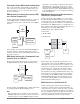
RMH Installation and Removal on a DIN Rail Modular Backplane Connector The picture on the right shows the Modular Backplane Connector, both front and rear view. The rear view is bringing in to focus a metal clip. If the DIN rail is grounded the Modular Backplane Connector and the module connected to it will be also (recommended).
Module Removal To remove a module from the Modular Backplane Connector find the red tab protruding from the bottom of the module and pull back on it as shown to the right. While pulling back on the red tab the two mounting posts will release the module where the module can then be lifted up and out of the Modular Backplane Connector.
Wiring High Density Module (R M H x - x x x x - x x x x) Slot A Slot B Slot D Slot E Configuration Inputs Universal, RTD and Thermistor Inputs 1-4 5-8 9 - 12 13 - 16 S1 R1 S2 R2 S3 R3 S4 R4 S5 R5 S6 R6 S7 R7 S8 R8 S9 R9 S10 R10 S11 R11 S12 R12 S13 R13 S14 R14 S15 R15 S16 R16 S_ (RTD), thermocouple -, volts - , mA -, potentiometer wiper or thermistor R_ (RTD), thermocouple +, volts +, mA +, potentiometer or thermistor Universal/Thermistor Input Part # Digits 5, 6, 7 Input 1-4: RMH _ - [1,2] _
High Density Module (R M H x - x x x x - x x x x) Slot A Slot B Slot D Slot E Configuration Tri-State Process/Retransmit Outputs Outputs (cont.
RMH Module - Front View Standard Connector Slot D Slot E Slot A Slot B Slot C Slot C 98 99 power Watlow EZ-ZONE ® RMH Module • 22 • Chapter 2 Install and Wire
RMH System Isolation Blocks Mechanical Relay, Solid-State Relay, Outputs Digital Inputs & Outputs, Process Outputs Low-voltage Isolation Analog Input 1 - 16 Safety Isolation Safety Isolation Controller Power Supply 20.4 to 30.8VÎ (dc) 20.4 to 30.
Warning: ç Use National Electric (NEC) or other country-specific standard wiring and safety practices when wiring and connecting this controller to a power source and to electrical sensors or peripheral devices. Failure to do so may result in damage to equipment and property, and/or injury or loss of life. High Density Module Wiring (RMHx-xxxx-xxxx) Low Power RMH- ALL Model Numbers • 20.4 to 30.
Warning: ç Inputs 1 through 16 Potentiometer CW Use National Electric (NEC) or other country-specific standard wiring and safety practices when wiring and connecting this controller to a power source and to electrical sensors or peripheral devices. Failure to do so may result in damage to equipment and property, and/or injury or loss of life. CCW CW CCW CW Note: CCW CW Maximum wire size termination and torque rating: • 0.0507 to 3.30 mm2 (30 to 12 AWG) single-wire termination or two 1.
Warning: ç Process Inputs 1 through 16 RMH Part # Digit 5, 6, 7, 8 is 1 Use National Electric (NEC) or other country-specific standard wiring and safety practices when wiring and connecting this controller to a power source and to electrical sensors or peripheral devices. Failure to do so may result in damage to equipment and property, and/or injury or loss of life. - Slot A, B, D, E + + Slot A, B, D, E - S_ + R_ Maximum wire size termination and torque rating: • 0.0507 to 3.
Warning: ç Digital Outputs 1 - 12 RMH Part # Digit 7, 8 is C Use National Electric (NEC) or other country-specific standard wiring and safety practices when wiring and connecting this controller to a power source and to electrical sensors or peripheral devices. Failure to do so may result in damage to equipment and property, and/or injury or loss of life.
Warning: ç Open Collector Wiring Example Using DO 1-12 Use National Electric (NEC) or other country-specific standard wiring and safety practices when wiring and connecting this controller to a power source and to electrical sensors or peripheral devices. Failure to do so may result in damage to equipment and property, and/or injury or loss of life. Collector Outputs B_ Fuse D_ Diode D_ Maximum wire size termination and torque rating: • 0.0507 to 3.
Warning: ç Quad 2A SSR Outputs 1-4, 7-10 RMH Part # Digit 7, 8 is L Use National Electric (NEC) or other country-specific standard wiring and safety practices when wiring and connecting this controller to a power source and to electrical sensors or peripheral devices. Failure to do so may result in damage to equipment and property, and/or injury or loss of life.
Warning: ç Use National Electric (NEC) or other country-specific standard wiring and safety practices when wiring and connecting this controller to a power source and to electrical sensors or peripheral devices. Failure to do so may result in damage to equipment and property, and/or injury or loss of life. Note: Maximum wire size termination and torque rating: • 0.0507 to 3.30 mm2 (30 to 12 AWG) single-wire termination or two 1.31 mm2 (16 AWG) • 0.8 Nm (7.0 in-lb.
ç Use National Electric (NEC) or other country-specific standard wiring and safety practices when wiring and connecting this controller to a power source and to electrical sensors or peripheral devices. Failure to do so may result in damage to equipment and property, and/or injury or loss of life. EZ ZONE R RM 1 D D 98 99 CF CD CE CZ CX CY Note: Maximum wire size termination and torque rating: • 0.0507 to 3.30 mm2 (30 to 12 AWG) single-wire termination or two 1.31 mm2 (16 AWG) • 0.8 Nm (7.0 in-lb.
Warning: ç Use National Electric (NEC) or other country-specific standard wiring and safety practices when wiring and connecting this controller to a power source and to electrical sensors or peripheral devices. Failure to do so may result in damage to equipment and property, and/or injury or loss of life. Note: Maximum wire size termination and torque rating: • 0.0507 to 3.30 mm2 (30 to 12 AWG) single-wire termination or two 1.31 mm2 (16 AWG) • 0.8 Nm (7.0 in-lb.
Wiring a Serial EIA-485 Network Do not route network wires with power wires. Connect network wires in daisy-chain fashion when connecting multiple devices in a network. A network using Watlow's Standard Bus and an RUI/Gate way. EZ-ZONE® RMH A termination resistor is required. Place a 120 Ω resistor across T+/R+ and T-/R- of the last controller on a network. Only one protocol per port is available at a time: either Modbus RTU or Standard Bus.
Connecting and Wiring the Modules RMH Module Connections third power supply could be used. The RMH module can be installed as a stand-alone limit controller or can be interconnected on the DIN rail as shown below with other RM family modules. When modules are connected together as shown, power and communications are shared between modules over the modular backplane interconnection. Therefore, bringing the necessary power and communications wiring to any one connector in slot C is sufficient.
Conventions Used in the Menu Pages [1] = 1 [0] = 0 [i] = i [r] = r To better understand the menu pages that follow review the naming conventions used. When encountered throughout this document, the word "default" implies as shipped from the factory.
the header as Modbus and notice that it lists register 380. Because this parameter is a float it is actually represented by registers 381 (low order bytes) and 381 (high order bytes). Because the Modbus specification does not dictate which register should be high or low order Watlow provides the user the ability to swap this order (Setup Page, Com Menu) from the default low/high [lohi] to high/low [ hilo] .
3 Chapter 3: Operations Pages Navigating the Operations Page To navigate to the Operations Page using the RUI, follow the steps below: 1. From the Home Page, press both the Up ¿ and Down ¯ keys for three seconds. [``Ai] will appear in the upper display and [oPEr] will appear in the lower display. 2. Press the Up ¿ or Down ¯ key to view available menus. the Up ¿ or Down ¯ key to select and then press the Advance Key ‰ to enter. 5. Press the Up ¿ or Down ¯ key to move through available menu prompts. 6.
[`LgC] [oPEr] Logic Menu [```1] [`LgC] Logic (1 to 24) [`Su;A] Source Value A [`Su;b] Source Value B [`Su;C] Source Value C [`Su;d] Source Value D [`Su;E] Source Value E [`Su;F] Source Value F [`Su;g] Source Value G [`Su;h] Source Value H [``o;u] Output Value [MAt] [oPEr] Math Menu [```1] [MAt] Math (1 to 24) [`Su;A] Source Value A [`Su;b] Source Value B [`Su;C] Source Value C [`Su;d] Source Value D [`Su;E] Source Value E [oFSt] Offset [``o;u] Output Value Wa
RM High Density Module Display Parameter Name Description Range • Operations Page Default Modbus Relative Address CIP Class Instance Attribute hex (dec) Data Profibus Parameter Type Index ID & Read/ Write [``Ai] [oPEr] Analog Input Menu -1,999.000 to 9,999.000°F or units -1,128.000 to 5,537.000°C ---- 380 [offset 90] 0x68 (104) 1 to 16 1 0 4001 float R -1,999.000 to 9,999.000°F [``pu;f] Analog Input (1 to 16) Filtered Analog Input or units [ Pu.F] Value -1,128.000 to 5,537.
RM High Density Module Parameter Name Description Display Range • Operations Page Default Modbus Relative Address CIP Class Instance Attribute hex (dec) Data Profibus Parameter Type Index ID & Read/ Write [`Su;c] [ Sv.c] Process Value (1 to 16) -1,999.000 to 9,999.000°F Source Value C or units View the value of Source C. -1,128.000 to 5,537.000°C ---- 8254 [offset 70] 0x7E (126) 1 to 16 0x12 (18) ---- 26018 float R [`Su;d] [ Sv.d] Process Value (1 to 16) -1,999.000 to 9,999.
RM High Density Module Parameter Name Description Display Range • Operations Page Default Modbus Relative Address CIP Class Instance Attribute hex (dec) Data Profibus Parameter Type Index ID & Read/ Write [Mon] [oPEr] Monitor Menu [C;MA] [C.MA] Monitor (1 to 16) Control Mode Active View the control mode currently in effect. [`off] Off (62) [AUto] Auto (10) [MAn] Manual (54) Off 4100 [offset 70] 0x97 (151) 1 to 16 2 ---- 8002 uint R [`h;Pr] [ h.
RM High Density Module Display Parameter Name Description Range • Operations Page Default Modbus Relative Address CIP Class Instance Attribute hex (dec) Data Profibus Parameter Type Index ID & Read/ Write [`C;SP] [ C.SP] Control Loop (1 to 16) Closed Loop Set Point Set the set point that the controller will automatically control to. Low Set Point to High Set Point (Setup Page) 75.0°F or units 24.0°C 5220 [offset 80] 0x6B (107) 1 to 16 1 39 7001 float RWES [`id;S] [ id.
RM High Density Module Parameter Name Description Display [`o;SP] [ o.SP] Control Loop (1 to 16) Open Loop Set Point Set a fixed level of output power when in manual (open-loop) mode. Range • Operations Page Default Modbus Relative Address CIP Class Instance Attribute hex (dec) Data Profibus Parameter Type Index ID & Read/ Write -100.0 to 100.0% 0.0 5222 [offset 80] 0x6B (107) 1 to16 2 41 7002 float RWES -1,999.000 to 9,999.000°F or units -1,128.000 to 5,537.000°C 32.0 °F or units 0.
RM High Density Module Display Parameter Name Description Range • Operations Page Default Modbus Relative Address CIP Class Instance Attribute hex (dec) Data Profibus Parameter Type Index ID & Read/ Write No Display Alarm (1 to 24) Silenced Read this register to determine if the alarm is silenced No (59) Yes (106) None 2680 [offset 60] 0x6D (109) 1 to 24 0x0B (11) ---- 9011 uint R No Display Alarm (1 to 24) Clearable Read to determine if an alarm can be cleared No (59) Yes (106) None
RM High Density Module Parameter Name Description Display Range • Operations Page Default Modbus Relative Address CIP Class Instance Attribute hex (dec) Data Profibus Parameter Type Index ID & Read/ Write [`CPE] [oPEr] Compare Menu [`Su;A] [ Su.A] Compare (1 to 24) Source Value A View the value of Source A. -1,999.000 to 9,999.000°F or units -1,128.000 to 5,537.000°C 11272 [offset 40] 0x80 (128) 1 to 24 7 ---- 28007 float R [`Su;b] [ Su.
RM High Density Module Parameter Name Description Display No Display Timer (1 to 24) Error Read reported cause for timer error Range • Operations Page Default Modbus Relative Address CIP Class Instance Attribute hex (dec) Data Profibus Parameter Type Index ID & Read/ Write None (61) Open (65) Shorted (127) Measurement Error (140) Bad Cal Data (139) Ambient Error (9) RTD Error (141) Fail (32) Math Error (1423) Not Sourced (246) Stale (1617) 13214 [offset 50] 0x83 (131) 1 to 24 0x12 (18) ----
RM High Density Module Parameter Name Description Display Range • Operations Page Default Modbus Relative Address CIP Class Instance Attribute hex (dec) Data Profibus Parameter Type Index ID & Read/ Write [`Su;C] [ Su.C] Logic (1 to 24) Source Value C View the value of Source C. [`off] Off (62) [``on] On (63) 9392 [offset 80] 0x7F (127) 1 to 24 0x1B (27) ---- 27027 uint R [`Su;d] [ Su.d] Logic (1 to 24) Source Value D View the value of Source D.
RM High Density Module Display Parameter Name Description Range • Operations Page Default Modbus Relative Address CIP Class Instance Attribute hex (dec) Data Profibus Parameter Type Index ID & Read/ Write [`Su;d] [ Su.d] Math (1 to 24) Source Value D View the value of Source D. -1,999.000 to 9,999.000°F or units -1,128.000 to 5,537.000°C 6576 [offset 70] 0x7D (125) 1 to 24 0x13 (19) ---- 25019 float RWES [`Su;E] [ Su.E] Math (1 to 24) Source Value E View the value of Source E.
4 Chapter 4: Setup Pages Navigating the Setup Page To navigate to the Setup Page using the RUI, follow the steps below: 1. From the Home Page, press and hold both the Up ¿ and Down ¯ keys for six seconds. [``Ai] will appear in the upper display and [`Set] will appear in the lower display. Note: If keys are released when [OPEr] is displayed, press the Infinity Key ˆ or reset key to exit and repeat until [`Set] is displayed. 2. Press the Up ¿ or Down ¯ key to view available menus. 4.
[`L;dE] Open Loop Detect Enable [`L;dt] Open Loop Detect Time [`L;dd] Open Loop Detect Deviation [``rp] Ramp Action [`r;SC] Ramp Scale [`r;rt] Ramp Rate [`l;sp] Set Point Closed Limit Low [`h;sp] Set Point Closed Limit High [`C;sp] Closed Loop Set Point [`id;s] Idle Set Point [sp;lo] Set Point Open Limit Low [sp;hi] Set Point Open Limit High [`o;sp] Open Loop Set Point [`C;m] User Control Mode [otpt] [`Set] Output Menu [```1] [otpt] Output (1 to 12) [``Fn]
RM High Density Module Display Parameter Name Description • Range Setup Page Default Modbus Relative Address CIP Class Instance Attribute hex (dec) Profibus Parameter Index ID Data Type & Read/ Write [``Ai] [`Set] Analog Input Menu [`Sen] [ SEn] Analog Input (1 to 16) Sensor Type Set the analog sensor type to match the device wired to this input. Note: There is no open-sensor detection for process inputs.
RM High Density Module Display Parameter Name Description • Range Setup Page Default Modbus Relative Address CIP Class Instance Attribute hex (dec) Profibus Parameter Index ID Data Type & Read/ Write [`off] Off (62) [Low] Low (53) Off 438 0x68 (104) 1 to 16 [offset 90] 0x1E (30) 10 4030 uint RWE -100.0 to 1,000.0 0.
RM High Density Module Display Parameter Name Description [``Ain] Analog Input (1 to 16) Value [ Ain] View the process value. Note: Ensure that the Error Status (below) indicates no error (61) when reading this value using a field bus protocol. If an error exists, the last known value prior to the error occurring will be returned. [`i;er] [ i.Er] • Range Setup Page Default -1,999.000 to 9,999.000°F or units -1,128.000 to 5,537.
RM High Density Module Display Parameter Name Description • Range Setup Page Default Modbus Relative Address CIP Class Instance Attribute hex (dec) Profibus Parameter Index ID Data Type & Read/ Write [`Si;A] [ Si.A] Process Value (1 to 16) Source Instance A Set the instance of the function selected above. 1 to 250 1 8230 [offset 70] 0x7E (126) 1 to 16 6 ---- 26006 uint RWES [SFn;b;] [SFn.
RM High Density Module Display Parameter Name Description • Range Setup Page Default Modbus Relative Address CIP Class Instance Attribute hex (dec) Profibus Parameter Index ID Data Type & Read/ Write [SFn;E] [SFn.E] Process Value (1 to 16) Source Function E Set the type of function that will be used for this source.
RM High Density Module Display Parameter Name Description • Range Setup Page Default Modbus Relative Address CIP Class Instance Attribute hex (dec) Profibus Parameter Index ID Data Type & Read/ Write [p;unt] [P.unt] Process Value (1 to 16) Pressure Units Set the units that will be applied to the source.
RM High Density Module Display Parameter Name Description • Range Setup Page Default [``Fn] [ Fn] Digital Output (1 to 12) Function Select what function will drive this output.
RM High Density Module Parameter Name Description Display • Range Setup Page Default [`o;Ct] [ o.Ct] Digital Output (1 to 12) [`Ftb] Fixed Time Base (34) Control [`utb] Variable Time Base Set the output control type. (103) This parameter is only used with PID control, but can be set anytime. [`o;tb] [ o.tb] Digital Output (1 to 12) 0.1 to 60.0 for switched DC/ Time Base SSR, 5.0 to 60.0 for mechanSet the time base for fixedical relays time-base control. [`o;Lo] [ o.
RM High Density Module Display Parameter Name Description • Range Setup Page Default Modbus Relative Address CIP Class Instance Attribute hex (dec) Profibus Parameter Index ID Data Type & Read/ Write None 2190 [offset 20] 0x6E (110) 1 to 24 6 ---- 10006 uint RWES 1 2182 [offset 20] 0x6E (110) 1 to 24 2 ---- 10002 uint RWES Action (1 to 24) 0 to 16 Source Zone A Set the zone of the function selected above.
RM High Density Module Display Parameter Name Description • Setup Page Range Default [`Si;A] [ Si.A] Control Loop (1 to 16) Source Instance A Set the instance of the function selected above. 1 to 16 1 [`h;Ag] [ h.Ag] Control Loop (1 to 16) Heat Algorithm Set the heat control method. [`oFF] Off (62) [`Pid] PID (71) [on;of] On-Off (64) PID [`C;Ag] [ C.Ag] Control Loop (1 to 16) [`oFF] Off (62) Cool Algorithm [`Pid] PID (71) Set the cool control method. [on;of] On-Off (64) [`C;Cr] [ C.
RM High Density Module Display Parameter Name Description • Setup Page Range Default Modbus Relative Address [``dB] [ db] Control Loop (1 to 16) Dead Band Set the offset to the proportional band. With a negative value, both heating and cooling outputs are active when the process value is near the set point. A positive value keeps heating and cooling outputs from fighting each other. -1,000.0 to 1,000.0 °F or units -555.556 to 555.556 °C 0.0 4118 [offset 70] [t;tUn] [t.
RM High Density Module Display Parameter Name Description • Setup Page Range Default CIP Class Instance Attribute hex (dec) Profibus Parameter Index ID Data Type & Read/ Write 5260 [offset 80] 0x6B (107) 1 to 16 0x15 (21) 38 7021 uint RWES None [none] None (61) [``Ai] Analog Input (142) [Curr] Current (22) [`C;pr] Cool Power (161) [`h;pr] Heat Power (160) [pwr] Power (73) [`lnr] Linearization (238) [mat] Math (240) [``Pu] Process Value (241) [`sp;C] Set Point Closed (242) [`sp;o] Set Point Op
RM High Density Module Display Parameter Name Description • Range Setup Page Default Modbus Relative Address CIP Class Instance Attribute hex (dec) Profibus Parameter Index ID Data Type & Read/ Write [FAiL] [FAiL] Control Loop (1 to 16) [`oFF] Off, sets output power User Input Error Failure to 0% (62) Select what the controller [bPLS] Bumpless transfer outputs will do when an maintains same output input error switches control power, if it was less than to manual mode.
RM High Density Module Display Parameter Name Description • Range Setup Page Default Modbus Relative Address CIP Class Instance Attribute hex (dec) Profibus Parameter Index ID Data Type & Read/ Write [`r;rt] [ r.rt] Control Loop (1 to 16) Ramp Rate Set the rate for the set point ramp. Set the time units for the rate with the Ramp Scale parameter. 0.0 to 9,999.000°F or units 0.0 to 5,555.000°C 1.0°F or units 1.
RM High Density Module Parameter Name Description Display • Range Setup Page Default Modbus Relative Address CIP Class Instance Attribute hex (dec) Profibus Parameter Index ID Data Type & Read/ Write [otpt] [`Set] Output Menu [``Fn] [ Fn] Output Digital(1 to 12) Function Select what function will drive this output.
RM High Density Module Display Parameter Name Description • Range Setup Page Default Fixed Time Base Modbus Relative Address CIP Class Instance Attribute hex (dec) Profibus Parameter Index ID Data Type & Read/ Write [`o;Ct] [ o.Ct] Output Digital (1 to 12) [`Ftb] Fixed Time Base (34) Control [`utb] Variable Time Base Set the output control type. (103) This parameter is only used with PID control, but can be set anytime. 1822 [offset 30] 0x6A (106) 1 to 12 2 75 6002 uint RWES [`o;tb] [ o.
RM High Density Module Display Parameter Name Description • Range Setup Page Default Modbus Relative Address CIP Class Instance Attribute hex (dec) Profibus Parameter Index ID Data Type & Read/ Write [``Fn] [ Fn] Output Process (1 to 3, 7 to 9) Function ** Set the type of function that will drive this output.
RM High Density Module Parameter Name Description Display • Range Setup Page Default Modbus Relative Address CIP Class Instance Attribute hex (dec) Profibus Parameter Index ID Data Type & Read/ Write [`r;Lo] [ r.Lo] Output Process(1 to 3, 7 -1,999.000 to 9,999.000°F or to 9) units Range Low ** -1,128.000 to 5,537.000°C Use to set the minimum value in process units. This will correspond with the Scale Low value. 0.
RM High Density Module Display Parameter Name Description • Range Setup Page Default Modbus Relative Address CIP Class Instance Attribute hex (dec) Profibus Parameter Index ID Data Type & Read/ Write [`A;hy] [ A.hy] Alarm (1 to 24) 0.001 to 9,999.000°F or units Hysteresis 0.001 to 5,555.000°C Set the hysteresis for an alarm. This determines how far into the safe region the process value needs to move before the alarm can be cleared. 1.0°F or units 1.
RM High Density Module Display Parameter Name Description • Setup Page Range Default Modbus Relative Address CIP Class Instance Attribute hex (dec) Profibus Parameter Index ID Data Type & Read/ Write Off 2674 [offset 60] 0x6D (109) 1 to 24 8 28 9008 uint RWES [`oFF] Off (62) [``on] On (63) Off 2670 [offset 60] 0x6D (109) 1 to 24 6 29 9006 uint RWES Alarm (1 to 24) Display Display an alarm message when an alarm is active.
RM High Density Module Display Parameter Name Description • Setup Page Range Default Modbus Relative Address CIP Class Instance Attribute hex (dec) Profibus Parameter Index ID Data Type & Read/ Write [`Lnr] [`Set] Linearization Menu Off 14388 0x86 (134) [offset 70] 1 to 24 5 120 34005 uint RWES [nonE] None (61) [``Ai] Analog Input (142) [CUrr] Current (22) [`C;Pr] Cool Power, Control Loop (161) [`h;Pr] Heat Power, Control Loop (160) [PWr] Power, Control Loop (73) [`Lnr] Linearization (238) [
RM High Density Module Display Parameter Name Description • Range Setup Page Default Modbus Relative Address CIP Class Instance Attribute hex (dec) Profibus Parameter Index ID Data Type & Read/ Write [`iP;2] [ ip.2] Linearization (1 to 24) Input Point 2 Set the value that will be mapped to output 2. -1,999.000 to 9,999.000 °F or units -1,128.333 to 5537.223 °C 1.0 14396 0x86 (134) [offset 70] 1 to 24 9 124 34009 float RWES [`oP;2] [ op.
RM High Density Module Display Parameter Name Description • Range Setup Page Default Modbus Relative Address CIP Class Instance Attribute hex (dec) Profibus Parameter Index ID Data Type & Read/ Write [`iP;8] [ ip.8] Linearization (1 to 24) Input Point 8 Set the value that will be mapped to output 8. -1,999.000 to 9,999.000 °F or units -1,128.333 to 5537.223 °C 7.0 14408 0x86 (134) [offset 70] 1 to 24 0xF (15) 136 34015 float RWES [`oP;8] [ op.
RM High Density Module Display Parameter Name Description • Range Setup Page Default Modbus Relative Address CIP Class Instance Attribute hex (dec) Profibus Parameter Index ID Data Type & Read/ Write [SFn;A] [SFn.A] Compare (1 to 24) Source Function A Set the type of function that will be used for this source.
RM High Density Module Parameter Name Description Display [`Er;h] [ Er.
RM High Density Module Display Parameter Name Description • Range Setup Page Default Modbus Relative Address CIP Class Instance Attribute hex (dec) Profibus Parameter Index ID Data Type & Read/ Write [`S2;A] [ SZ.A] Timer (1 to 4) 0 to 16 Source Zone A Set the zone of the function selected above. 0 13188 0x83 (131) [offset 50] 1 to 24 5 ---- 31005 uint RWES [sas;A] [SAS.A] Timer (1 to 4) [high] High (37) Source Active State A [LoW] Low (53) Set what state will be read as on.
RM High Density Module Display Parameter Name Description • Range Setup Page Default Modbus Relative Address CIP Class Instance Attribute hex (dec) Profibus Parameter Index ID Data Type & Read/ Write [sas;b] [SAS.b] Timer (1 to 24) [high] High (37) Source Active State B [LoW] Low (53) Set what state will be read as on. High 13202 0x83 (131) [offset 50] 1 to 24 0xC (12) ---- 31012 uint RWES [``ti] [ ti] Timer (1 to 24) 0.0 to 9,999.0 Time Set the time span that will be measured. 1.
RM High Density Module Display Parameter Name Description • Range Setup Page Default Modbus Relative Address CIP Class Instance Attribute hex (dec) Profibus Parameter Index ID Data Type & Read/ Write [`S2;A] [ SZ.A] Counter (1 to 24) 0 to 16 Source Zone A Set the zone of the function selected above. 0 12228 0x82 (130) [offset 40] 1 to 24 5 ---- 30005 uint RWES [sas;A] [SAS.A] Counter (1 to 24) Source Active State A Set what output state will indicate on.
RM High Density Module Parameter Name Description Display • Range Setup Page Default Modbus Relative Address CIP Class Instance Attribute hex (dec) Profibus Parameter Index ID Data Type & Read/ Write [trgt] [trgt] Counter (1 to 24) 0 to 9,999 Target Value Set the value that will turn the output value on.
RM High Density Module Display Parameter Name Description • Range Setup Page Default Modbus Relative Address CIP Class Instance Attribute hex (dec) Profibus Parameter Index ID Data Type & Read/ Write [SFn;A] [SFn.A] Logic (1 to 24) Source Function A Set the type of function that will be used for this source.
RM High Density Module Display Parameter Name Description • Range Setup Page Default Modbus Relative Address CIP Class Instance Attribute hex (dec) Profibus Parameter Index ID Data Type & Read/ Write [SFn;b] [SFn.b] Logic (1 to 24) Source B Function Set the type of function that will be used for this source.
RM High Density Module Display Parameter Name Description • Range Setup Page Default Modbus Relative Address CIP Class Instance Attribute hex (dec) Profibus Parameter Index ID Data Type & Read/ Write [SFn;C] [SFn.C] Logic (1 to 24) Source Function C Set the type of function that will be used for this source.
RM High Density Module Display Parameter Name Description • Range Setup Page Default Modbus Relative Address CIP Class Instance Attribute hex (dec) Profibus Parameter Index ID Data Type & Read/ Write [SFn;D] [SFn.d] Logic (1 to 24) Source Function D Set the type of function that will be used for this source.
RM High Density Module Display Parameter Name Description • Range Setup Page Default Modbus Relative Address CIP Class Instance Attribute hex (dec) Profibus Parameter Index ID Data Type & Read/ Write [SFn;E] [SFn.E] Logic (1 to 24) Source Function E Set the type of function that will be used for this source.
RM High Density Module Display Parameter Name Description [SFn;F] Logic (1 to 24) [ SFn.F] Source Function F Set the type of function that will be used for this source.
RM High Density Module Display Parameter Name Description • Range Setup Page Default Modbus Relative Address CIP Class Instance Attribute hex (dec) Profibus Parameter Index ID Data Type & Read/ Write [SFn;g] [SFn.g] Logic (1 to 24) Source Function G Set the type of function that will be used for this source.
RM High Density Module Display Parameter Name Description [SFn;h] Logic (1 to 24) [ SFn.h] Source Function H Set the type of function that will be used for this source.
RM High Density Module Parameter Name Description Display • Setup Page Range Default Modbus Relative Address CIP Class Instance Attribute hex (dec) Profibus Parameter Index ID Data Type & Read/ Write [MAt] [`Set] Math Menu [``Fn] [ Fn] Math (1 to 24) Function Set the operator that will be applied to the sources.
RM High Density Module Display Parameter Name Description • Range Setup Page Default Modbus Relative Address CIP Class Instance Attribute hex (dec) Profibus Parameter Index ID Data Type & Read/ Write [SFn;b;] [SFn.b] Math (1 to 24) Source Function B Set the type of function that will be used for this source.
RM High Density Module Display Parameter Name Description • Range Setup Page Default Modbus Relative Address CIP Class Instance Attribute hex (dec) Profibus Parameter Index ID Data Type & Read/ Write [SFn;D] [SFn.d] Math (1 to 24) Source Function D Set the type of function that will be used for this source.
RM High Density Module Display Parameter Name Description • Range Setup Page Default CIP Class Instance Attribute hex (dec) Profibus Parameter Index ID Data Type & Read/ Write 1 6558 [offset 70] 0x7D (125) 1 to 24 0xA (10) ---- 25010 uint RWES Math (1 to 24) 0 to 16 Source Zone E Set the zone of the function selected above. 0 6568 [offset 70] 0x7D (125) 1 to 24 0xF (15) ---- 25015 uint RWES [`S;Lo] [ S.Lo] Math (1 to16) -1,999.000 to 9,999.
RM High Density Module Parameter Name Description Display [`FiL] [ FiL] Math (1 to 24) Filter Filtering smooths out the output signal of this function block. Increase the time to increase filtering. • Range Setup Page Default Modbus Relative Address CIP Class Instance Attribute hex (dec) Profibus Parameter Index ID Data Type & Read/ Write 0.0 to 60.0 seconds 0.
RM High Density Module Display Parameter Name Description • Range Setup Page Default Modbus Relative Address CIP Class Instance Attribute hex (dec) Profibus Parameter Index ID Data Type & Read/ Write [USr;S] [USr.S] Global User Settings Save Save all of this controller's settings to the selected set. [none] None (61) [SEt1] User Set 1 (101) [SEt2] User Set 2 (102) None 26 0x65 (101) 1 0x0E (14) 93 1014 uint W [USr;r] [USr.
5 Chapter 5: Factory Pages Navigating the Factory Page To navigate to the Factory Page using the RUI, follow the steps below: 5. Press the Up ¿ or Down ¯ key to move through available menu prompts. 1. From the Home Page, press and hold both the Advance ‰ and Infinity ˆ keys for six seconds. 6. Press the Infinity Key ˆ to move backwards through the levels: parameter to submenu; submenu to menu; menu to Home Page. 2. Press the Up ¿ or Down ¯ key to view available menus. 7.
RM High Density Module Display Parameter Name Description • Factory Page Modbus Relative Address CIP Class Instance Attribute hex (dec) Data Profibus Parameter Type Index ID & Read/ Write Range Default [nonE] None (61) [`Pro] Process (75) [`i;CA] Calibration Offset (1196) [`C_F] Display Units (156) [USr;r] User Settings Restore (227) [`A;Lo] Alarm Low Set Point (42) [`A;hi] Alarm High Set Point (78) [`A;hy] Alarm Hysteresis (97) [stpt] Set Point () [aC;pu] Active Process Value (25) [aC;sp] Active S
RM High Density Module Display Parameter Name Description • Range Factory Page Default Modbus Relative Address CIP Class Instance Attribute hex (dec) Data Profibus Parameter Type Index ID & Read/ Write [`LoC] [FCty] Security Setting Menu [LoC;o] [LoC.o] Security Setting Operations Page Change the security level of the Operations Page. 1 to 3 2 ---- ---- ---- ---- ---- [pas;e] [LoC.P] Security Setting Password Enable Turn security features on or off.
RM High Density Module Display Parameter Name Description • Range Factory Page Default Modbus Relative Address CIP Class Instance Attribute hex (dec) Data Profibus Parameter Type Index ID & Read/ Write [pas;u] [PAS.u] Security Setting 10 to 999 User Password Used to acquire access to menus made available through the Locked Access Level setting. 63 ---- ---- ---- ---- ---- [pas;a] [PAS.A] Security Setting Administrator Password Used to acquire full access to all menus.
RM High Density Module Display Parameter Name Description [dAtE] [dAtE] Diagnostics Menu Date of Manufacture Display the date code in YYWW format No Display Diagnostics Menu Hardware ID Read the hardware ID.
6 Chapter 6: Features Saving and Restoring User Settings. . . . . . . . . . . . . . . . . . . . . . . . . 101 Inputs . . . . . . . . . . . . . . . . . . . . . . . . . . . . . . . . . . . . . . . . . . . . . 101 Calibration Offset . . . . . . . . . . . . . . . . . . . . . . . . . . . . . . . . . . . . . . . . . 101 Calibration . . . . . . . . . . . . . . . . . . . . . . . . . . . . . . . . . . . . . . . . . . . . . .
6 Chapter 6: Features (cont.) Global Function. . . . . . . . . . . . . . . . . . . . . . . . . . . . . . . . . . . . . . . . . . . Logic Function . . . . . . . . . . . . . . . . . . . . . . . . . . . . . . . . . . . . . . . . . . . Math Function. . . . . . . . . . . . . . . . . . . . . . . . . . . . . . . . . . . . . . . . . . . . Timer Function. . . . . . . . . . . . . . . . . . . . . . . . . . . . . . . . . . . . . . . . . . . Counter Function . . . . . . . . . . . . . . . . . . . . . . . . . . . . . . .
Saving and Restoring User Settings Recording setup and operations parameter settings for future reference is very important. If you unintentionally change these, you will need to program the correct settings back into the controller to return the equipment to operational condition. After you program the controller and verify proper operation, use User Save Set [USr;S] (Setup Page, Global Menu) to save the settings into either of two files in a special section of memory.
Set Electrical Offset to 0 and Electrical Slope to 1 to restore factory calibration. Filter Time Constant Filtering smoothes an input signal by applying a first-order filter time constant to the signal. Filtering the displayed value makes it easier to monitor. Filtering the signal may improve the performance of PID control in a noisy or very dynamic system. Adjust the filter time interval with Filter Time [`FiL] (Setup Page, Analog Input Menu). Example: With a filter value of 0.
Select the low and high values with Range Low [`r;Lo] and Range High [`r;hi] (Setup Page, Analog Input Menu). Scale Low [`S;Lo] and Scale High [`S;hi]. Cool Output Curve The linearization function allows a user to re-linearize a value read from an analog input. There are 10 data points used to compensate for differences between the sensor value read (input point) and the desired value (output point).
perform a “bumpless” transfer [bPLS], switch power to output a preset fixed level [MAn], or turn the output power off. Bumpless transfer will allow the controller to transfer to the manual mode using the last power value calculated in the auto mode if the process had stabilized at a ±5 percent output power level for the time interval of Time Integral (Operations Page, Loop) prior to sensor failure, and that power level is less than 75 percent.
Note: Input Error Failure Mode [faIl] does not function in on-off control mode. The output goes off. In an application with one output assigned to heating and another assigned to cooling, each will have a separate proportional parameter. The heating parameter takes effect when the process temperature is lower than the set point, and the cooling parameter takes effect when the process temperature is higher than the set point.
Reduced Overshoot Set Point Proportional Band Proportional Band x 2 Cool Output Active Set Point Temperature Heat Output Active Temperature Heating Slows Negative Dead Band Time Adjust the dead band with Dead Band [``db] (Operations Page, Loop Menu). Time PID Control Dead Band In a PID application the dead bands above and below the set point can save an application’s energy and wear by maintaining process temperature within acceptable ranges.
what action it takes and whether it turns off automatically when the alarm condition is over. Configure alarm outputs in the Setup Page before setting alarm set points. Alarms do not have to be assigned to an output. Alarms can be monitored and controlled through the front panel or by using software. 50 percent output 3 ON, 3 OFF Process and Deviation Alarms 66 percent output 6 ON, 3 OFF Single Set Point Ramping Ramping protects materials and systems that cannot tolerate rapid temperature changes.
High Side Alarm Range Alarm High Set Point Temperature Alarm Hysteresis Normal Operating Range Alarm Hysteresis Low Side Alarm Range Alarm Low Set Point Time Alarm Set Points and Hysteresis Alarm Latching A latched alarm will remain active after the alarm condition has passed. It can only be deactivated by the user.
2 tory Page): • Lock Operations Page [LoC;o] sets the security level for the Operations Page. (default: 2) Note: The Home and Setup Page lockout levels are fixed and cannot be changed. • Lock Profiling Page [LoC;P] sets the security level for the Profiling Page. (default: 3) • Password Security Enable [ pas ; e ] will turn on or off the Password security feature. (default: off) • Read Lockout Security [rLoC] determines which pages can be accessed.
4. Execute the calculation defined below (7b or 8b) for either the User or Administrator. to get to the [`loC] menu. Again push the Advance ‰ key until the Password Enabled [ pas ; e ] prompt is visible. Lastly, push either the up or down key to turn it on. Once on, 4 new prompts will appear: 1. [loC; l] , Locked Access Level (1 to 5) correspond ing to the lockout table above. 2. [roll] , Rolling Password will change the Customer Code every time power is cycled. 3.
to) the Modbus address of a parameter within the controller. Assembly Working Addresses - Fixed addresses directly related to their associ ated "Assembly Definition Addresses" (e.g., As sembly Working Addresses 200 & 201 will as sume the parameter pointed to by Assembly Defi nition Addresses 40 & 41). When the Modbus address of a target parameter is stored in an "Assembly Definition Address" its corresponding working address will return that parameter’s actual value.
Software Configuration define the communications port on the PC to use. Using EZ-ZONE® Configurator Software To enable a user to configure the RMH control using a personal computer (PC), Watlow has provided free software for your use. If you have not yet obtained a copy of this software insert the CD (Controller Support Tools) into your CD drive and install the software.
lighted (address 6) to bring greater clarity to the control in focus. Any EZ-ZONE device on the network will appear in this window and would be available for the purpose of configuration or monitoring. After clicking on the control of choice simply click the next button once again. After clicking on Setup and then Analog Input 1 the next screen appears below. to that parameter will appear in the center column.
Although the RMH control now contains the configuration (because the previous discussion focused on doing the configuration on-line) it is suggested that after the configuration process is completed that the user save this file on the PC for future use. If for some reason someone inadvertently changed a setting without understanding the impact it would be easy and perhaps faster to download a saved configuration back to the control versus trying to figure out what was changed.
Function Block Descriptions Each of the next several pages graphically shows each of the RMH function blocks. Note that as you view each you will find text that is black and text that appears gray. The gray text represents inputs that are not currently available based on the function's defined use (red text). For instance when the defined use of the Analog Input function is set for RTD, TC Linearization will appear gray.
Process Value Function The Process Value (PV) function block accepts multiple inputs and performs a programmed math function to derive an output value with Filter and Offset values applied. It is assumed that no input error conditions apply. Some PV operations must be performed in the user's units. Functions may combine multiple inputs. Those inputs may have incompatible units from a logical point of view. As a result, unless otherwise indicated, the presentation of the output value is the same as Source A.
Ba ro Cr Cr os os Pre Al met s O s O ss tit ri Fu ve ve ur ude c Pr nc r P r B e U U es F Of tio oi an ni ni su ilt fs n nt d ts ts re er et Ba ro Cr Cr os os Pre Al met s O s O ss tit ri Fu ve ve ur ude c Pr nc r P r B e U U es F Of tio oi an ni ni su ilt fs n nt d ts ts re er et Source Function A Source Instance A Source Error A Source Function B Source Instance B Source Zone B Source Error B Source Function C Source Instance C Source Zone C Source Error C Source Function D Source Instance D Source Zone
Ba ro Cr Cr os os Pre Al met s O s O ss tit ri Fu ve ve ur ude c Pr nc r P r B e U U es F Of tio oi an ni ni su ilt fs n nt d ts ts re er et Source Function A Source Instance A Source Error A Source Function B Source Instance B Source Zone B Source Error B Source Function C Source Instance C Source Zone C Source Error C Source Function D Source Instance D Source Zone D Source Error D Source Function E Source Instance E Source Zone E Source Error E Ba ro Cr Cr os os Pre Al met s O s O ss tit ri Fu ve ve ur
Linearization Function An error, when read, can indicate any of the following: None, Open, Shorted, Measurement Error, Bad Cal Data, Ambient Error, RTD Error, Fail, Math Error, Not Sourced, Stale Fu Source Function A Source Instance A Source Zone A Source Error A O O In Out In ut In Out In Out In Out In Out In Out In Out In Out Inp utp pu pu pu pu pu pu pu pu pu pu pu pu pu pu pu pu pu pu ut ut Fu t P t P t P t P t P t P t P t P t P t P t P t P t P t P t P t P t P t P Po Po nc U oi oi oi oi oi oi oi oi o
Ou Ou tp tpu Ou ut L t H Ou tp ow igh tp ut P P ut Ti ow ow Co me er er nt Ba Sc Sc ro se al al e e l [ALM] Alarm Menu [SEt] Setup Page [A;ty] Alarm Type : Off, Deviation, Process [Sr;A] Alarm Source : Analog Input, Current, Power, Linearization, Math, Process Value, Variable [iS;A] Alarm Source Instance : 1 to 250 [S2;A] Alarm Source Zone : 0 to 16 Output Function Output Value Output Function Instance Error Output Source Zone Output Source Error [LooP] Control Loop : 1 to 16 [A;hy] Alarm Hysteresis : 0.
Digital Input/Output Function A A Al la A Al larmarm rm larm Al A A A a ar la la la A rm L H Sil C Al Con m H Ala Ala rm rm rm larm D ow igh ence lea ar tr y rm rm La B Sil D ela Se Se R r R m ol ste t lo e y t t e e Ty Lo re Lo Sid chi cki nci ispl Ti Poi Poi que que pe op sis gic es ng ng ng ay me nt nt st st Alarm Source Alarm Source Instance Alarm Source Zone Alarm Source Error Note: Input Value is passed to either profile event inputs or action function blocks.
Digital Input/Output Function (cont.) Action Function Output Value is determined by Source A and Digital Output Function The Action Function selected will execute when Source Function A = ON and Active Level = High. Based on a given input (Digital, Event output, Logic function, etc..), the Action function can cause other functions to occur. To name a few, starting and stopping a profile, silencing alarms, turn control loops off and placing alarms in nonalarm state.
Control Function Op Cl Clo S Se Lo Op en Au Re os se et t P Re H Co o ed d Po o m en Op Lo ea to m Re Cl ol TR T Op p E e t o tP os Lo Loo int int ote Lo n op Au te mo Us Inp Co U R TR un P en rro ed ro H ro op p O Op Se op Lo De Se te er u t P T H C ol -T U- U- e A o C Lo r C Lo I po ea po o T im ro L H pe e t tu D op t ea oo O UN TU T gg P t P Se Fa t E op lea op dle rti t H rti ol H im e t A l A utp E N UN re elt oi t P ilu rro Fix ete De ect Ram Ra R filin ow igh n L n Li Poi Con ne D o o D e D n n A a
Global Function [`SEt] Setup Page [`LgC] Logic Menu U U ser Li D ser Se Di ne i Se tti sp F sp tt ng la re lay ing s R y U qu P s e ni enc lai Sav sto ts y rs e re AC [Fn] Function : Off, AND, OR, Equal To, NAND, NOR, Not Equal To, Latch, RS Flip Flop [SFn;A] Source Function A : None, Alarm, Compare, Counter, Digital I/O, Profile Event Out A to H, Function Key, Limit, Logic, Special Function Output 1 to 4, Timer, Variable [Si;A] Source Instance A : 1 to 250 [S2;A] Source Zone A : 0 to 16 [SFn;b] Source
Function Source Function A Source Instance A Source Zone A Source Error A Source Value B Source Value C Source Value D Source Function C Source Instance C Source Zone C Source Error C Source Value G Source Function E Source Instance E Source Zone E Source Error E Source Function A Source Instance A Source Zone A Source Error A Source Value A Source Function B Source Instance B Source Zone B Source Error B Source Function D Source Instance D Source Zone D Source Error D Function Error Handling Sou
Function Source Function A Source Instance A Source Zone A Source Error A Source Value B Source Value C Source Function B Source Instance B Source Zone B Source Error B Source Value D Source Value E Source Value F Source Function C Source Instance C Source Zone C Source Error C Source Function E Source Instance E Source Zone E Source Error E Source Function A Source Instance A Source Zone A Source Error A Source Value A Source Function B Source Instance B Source Zone B Source Error B Source Functio
Function Source Function A Source Instance A Source Zone A Source Error A Source Value B [SFn;A] Source Function A : None, Analog Input, Current, Cool Power, Heat Power, Power, Linearization, Math, Process Value, Set Point Closed, Set Point Open, Variable [Si;A] Source Instance A : 1 to 250 Source Value C Source Value D [S2;A] Source Zone A : 0 to 16 Source Value E [SFn;b] Source Function B : None, Analog Input, Current, Cool Power, Heat Power, Power, Linearization, Math, Process Value, Closed Loop Se
Pr A l S R R es ti Fu Sca cal an ang sur tud nc le e H ge e H e U e U F Of tio Lo ig Lo ig ni ni ilt fs n w h w h ts ts er et Source Function A Source Instance A Source Zone A Source Error A Source Function B Source Instance B Source Zone B Source Error B Source Function C Source Instance C Source Zone C Source Error C Source Function D Source Instance D Source Zone D Source Error D Source Function E Source Instance E Source Zone E Source Error E Pr A l S R R es ti Fu Sca cal an ang sur tud nc le e H ge e
Pr A l S R R es ti Fu Sca cal an ang sur tud e e g e e l nc e O e tio Lo Hig Lo Hig Uni Uni Filt ffs n w h w h ts ts er et Source Function A Source Instance A Source Zone A Source Error A Source Function B Source Instance B Source Zone B Source Error B Source Function C Source Instance C Source Zone C Source Error C Pr A l S R R es ti Fu Sca cal an ang sur tud e e g e e l nc e O e tio Lo Hig Lo Hig Uni Uni Filt ffs n w h w h ts ts er et Source Function A Source Instance A Source Zone A Source Error A So
Pr A l S R R es ti Fu Sca cal an ang sur tud e e g e e l nc e O e tio Lo Hig Lo Hig Uni Uni Filt ffs n w h w h ts ts er et Source Function A Source Instance A Source Zone A Source Error A Source Function B Source Instance B Source Zone B Source Error B Source Function C Source Instance C Source Zone C Source Error C Source Function D Source Instance D Source Zone D Source Error D Source Function E Source Instance E Source Zone E Source Error E Pr A l S R R es ti Fu Sca cal an ang sur tud e e g e e l nc e
Pr A l S R R es ti Fu Sca cal an ang sur tud nc le e H ge e H e U e U F Of tio Lo ig Lo ig ni ni ilt fs n w h w h ts ts er et Source Function A Source Instance A Source Zone A Source Error A Source Function B Source Instance B Source Zone B Source Error B Source Function C Source Instance C Source Zone C Source Error C Source Function D Source Instance D Source Zone D Source Error D Source Function E Source Instance E Source Zone E Source Error E Pr A l S R R es ti Fu Sca cal an ang sur tud nc le e H ge e
Timer Function So S ur ou ce rce Ac A Ac ti cti tiv Fu ve S ve S e nc ta ta tio te te Tim Lev n A B e el So S ur ou ce rce Ac A Ac ti cti tiv Fu ve S ve S e nc ta ta tio te te Tim Lev n A B e el Source Function A Source Instance A Source Zone A Source Error A Source Function A Source Instance A Source Zone A Source Error A Source Value A Source Value B Source Function B Source Instance B Source Zone B Source Error B Elapsed Time Source Value A Source Value B Source Function B Source Instance B Sour
So S ur ou ce rce Ac A Ac ti cti tiv Fu ve S ve S e nc ta ta tio te te Tim Lev n A B e el Source Function A Source Instance A Source Zone A Source Error A Source Value A Source Value B Elapsed Time Source Function B Source Instance B Source Zone B Source Error B Output Value Error Timer On Pulse Timing Diagram of On Pulse with active state rising edge Source A (Run) [Sr;A] Source Active State A [SAS;A] : High Source Value A [uS;A] high low on Active Level [Leu] : High Output Value [o;u] off on Act
So S ur ou ce rce Ac A Ac ti cti tiv Fu ve S ve S e nc ta ta T tio te te im Lev A B n e el Source Function A Source Instance A Source Zone A Source Error A Source Value A Source Value B Elapsed Time Source Function B Source Instance B Source Zone B Source Error B Output Value Error Timer Delay Source A Source A Watlow EZ-ZONE ® RMH Module • 136 • Chapter 6 Features
So S ur ou ce rce Ac A Ac ti cti tiv Fu ve S ve S e nc ta ta T t tio e te im Lev n A B e el Source Function A Source Instance A Source Zone A Source Error A Source Value A Source Value B Elapsed Time Source Function B Source Instance B Source Zone B Source Error B Output Value Error Timer One Shot Watlow EZ-ZONE ® RMH Module • 137 • Chapter 6 Features
So S ur ou ce rce Ac A Ac ti cti tiv Fu ve S ve S e nc ta ta T t tio e te im Lev n A B e el Source Function A Source Instance A Source Zone A Source Error A Source Value A Source Value B Elapsed Time Source Function B Source Instance B Source Zone B Source Error B Output Value Error Timer Retentive Watlow EZ-ZONE ® RMH Module • 138 • Chapter 6 Features
Counter Function Variable Function Function counts up or down from Load Value and produces Output Value = On when Count = Target Value. Di An gi al D ta og at lV V aT U al al y ni ue ue pe ts Note: Count value clears on power loss. Load Value restored on power up.
Compare Function Er ro r Fu To Ha nc ler nd tio an lin n ce g Er ro r Fu To Ha nc ler nd tio an lin n ce g Source Value B Source Function A Source Instance A Source Zone A Source Error A Source Function B Source Instance B Output Value Source Zone B Source Error B Instances - 24 per RMH Error Source Function B Source Instance B Source Zone B Source Error B Source Function A Source Instance A Source Zone A Source Error A Source Value A Compare Overview Source Value A Source Value B Compare Greate
Custom Function Er ro r Fu To Ha nc ler nd tio an lin n ce g Source Function A Source Instance A Source Zone A Source Error A Source Function B Source Instance B Source Zone B Source Error B Pa Ins ra tan m c et e I er D Custom Overview Source Value A Source Value B Instances - 50 per RMH Compare Not Equal To [FAct] Factory Page [CUSt] Custom Menu Output Value [PAr] Parameter : None, Process, Calibration Offset, Display Units, User Settings Restore, Alarm Low Set Point, Alarm High Set Point, Alar
Diagnostic Function Part Number Software Revision Software Build Number Serial Number Diagnostics Overview Date of Manufacture Hardware ID Device Status Instances - 1 per RMH Device Name [FAct] Factory Page [diAg] Diagnostics Menu [Pn] Part Number: scrolls on display [rEu] Software Revision: 4.00, ... [S;bLd] Software Build Number : 0, 1, 2, ...
7 Chapter 10: Appendix Modbus - Programmable Memory Blocks The Modbus assembly contains 40 pointers to the parameters of your choosing starting at Modbus register 40 (shown on the following page). The pointers are 32-bits long so are stored in two sequential registers. As an example, if we want to move an alias to the analog input of the RMH (register 380) into register 40, we perform a multiple write command (0x10 function) of 380 into register 40 and 381 into register 41 as a single multi-write command.
Assembly Pointer Registers and Assembly Working Registers Definition Addresses Working Addresses Definition Addresses Working Addresses 40 & 41 200 & 201 120 & 121 280 & 281 42 & 43 202 & 203 122 & 123 282 & 283 44 & 45 204 & 205 124 & 125 284 & 285 46 & 47 206 & 207 126 & 127 286 & 287 48 & 49 208 & 209 128 & 129 288 & 289 50 & 51 210 & 211 130 & 131 290 & 291 52 & 53 212 & 213 132 & 133 292 & 293 54 & 55 214 & 215 134 & 135 294 & 295 56 & 57 216 & 217 136 & 137 296 & 2
Modbus Default Assembly Structure 40-119 Assembly Definition Addresses Default Pointers Assembly Working Addresses Assembly Definition Addresses Default Pointers Assembly Working Addresses Registers 40 & 41 Registers 200 & 201 Registers 80 & 81 Registers 240 & 241 Pointer 1 = 0 & 1 Hardware ID Registers 42 & 43 Pointer 2 = 0 & 1 Hardware ID Registers 44 & 45 Pointer 3 = 0 & 1 Hardware ID Registers 46 & 47 Pointer 4 = 0 & 1 Hardware ID Registers 48 & 49 Pointer 5 = 0 & 1 Hardware ID Registers 50
Modbus Default Assembly Structure 120-199 Assembly Definition Registers Default Pointers Assembly Working Registers Assembly Definition Registers Default Pointers Assembly Working Registers Registers 120 & 121 Registers 280 & 281 Registers 160 & 161 Registers 320 & 321 Pointer 41 = 0 & 1 Hardware ID Registers 122 & 123 Pointer 42 = 0 & 1 Hardware ID Registers 124 & 125 Pointer 43 = 0 & 1 Hardware ID Registers 126 & 127 Pointer 44 = 0 & 1 Hardware ID Registers 128 & 129 Pointer 45 = 0 & 1 Har
Troubleshooting Alarms, Errors and Module Issues Indication Description Possible Cause(s) Alarm won’t clear or reset Alarm will not clear or reset • Alarm latching is active with keypad or digital input • Alarm set to incorrect output Alarm won’t occur Alarm will not activate output • Alarm silencing is active • Alarm blocking is active • Alarm is set to incorrect output Corrective Action • Reset alarm when process is within range or disable latching • Set output to correct alarm source instance • A
Indication No Display Description No display indication or LED illumination Possible Cause(s) • • • • • Corrective Action Power to controller is off Fuse open Breaker tripped Safety interlock switch open Separate system limit control activated • Wiring error • Incorrect voltage to controller • Turn on power • Replace fuse • Reset breaker • Close interlock switch • Reset limit • Correct wiring issue • Apply correct voltage, check part number No Serial Communication Cannot establish serial communicatio
Indication RUI value to high [ual;h] Description Possible Cause(s) Value to high to be displayed in 4 digit LED display >9999 • Incorrect setup Corrective Action • Check scaling of source data Detection of and Rules Around Abnormal Sensor Conditions Inputs Detection of Abnormal Conditions Shorted No direct detection, Open loop firmware detection.
RMH Specifications Line Voltage/Power • 20.4 to 30.8Vı (ac/dc), 50/60Hz, ±5 percent • Power consumption: 7 W, 14VA • Any external power supply used should comply with a class 2 or SELV rating.
Input Type Max Error @ 25 Deg C Accuracy Range Low Accuracy Range High Thermistor Input (cont.) Units Input Type Max Error @ 25 Deg C Accuracy Range Low Accuracy Range High Units mA ac ±5 0 50 mAmps AC ±20 0 20000 Ohms Potentiometer, 1K range ±1 0 1000 Ohms Thermistor, 20K range Thermistor, 40K range ±40 0 40000 Ohms Operating Range Input Type Range Low Range High Units J -210 1200 DegC K -270 1371 DegC • • • • 0 to 40KΩ, 0 to 20KΩ, 0 to 10KΩ, 0 to 5KΩ 2.
Control Loops 16 total Compare 24 total Off, greater than, less than, equal, not equal, greater than or equal, less than or equal Counters 24 total Counts up or down loads, predetermined value on load signal.
EZ-ZONE Rail-Mount High Density Module Ordering Information High density module requires a Class 2 or SELV power supply 20.4 to 30.8 V ~(ac) / port provided for configuration with EZ-ZONE Configurator software.
Index [`A;bL] Alarm Blocking 70, 109 [AC;LF] AC Line Frequency 93 [A;Clr] Alarm Clear Request 70 [`ACt] Action Menu 39, 58 [A;dSP] Alarm Display 70 [`A;hi] Alarm High Set Point 42, 43, 69, 70, 108 [`A;hy] Alarm Hysteresis 69, 108 [``Ai] Analog Input Menu 38, 51 [`A;iS] Alarm Source Instance 68 [`A;LA] Alarm Latching 69, 109 [`A;Lg] Alarm Logic 69 [ALM] Alarm Menu 42, 68 [`A;Lo] Alarm Low Set Point 42, 69, 108 [`A;Sd] Alarm Sides 69 [`A;Si] Alarm Silencing 70, 109 [A;sir] Alarm Silence Request 70 [`A;st] Ala
alarms Blocking 70, 109 deviation 108 Display 70 Hysteresis 69, 108 Latching 69, 108 Logic 69 process 108 set points 108 Sides 69 Silencing 70, 109 Source 68 Type 68 Alarm Silence Request 70 Alarm State 70 Altitude Units 49, 50, 92 Analog Input Function 115 Analog Input Menu 38, 51 Assembly Definition Addresses 111 Assembly Working Addresses 111 auto (closed loop) control 105 Autotune Aggressiveness 62 Autotune Request 40 Autotune Set Point 40, 62 B Barometric Pressure 49 Baud Rate 94 Blocking 70, 109 bump
Lock Profiling Page 109 Logic 69 Logic Function 126 Logic Menu 46, 79 Loop Menu 40 Low Power Scale 58, 66 low range 103 low scale 103 Low Set Point Alarm 42, 69, 108 Loop 64, 103 M Manual Control Indicator Light 105 manual (open loop) control 105 Math Function 129 Math Menu 47, 88 Modbus Default Assembly Structure 80-119 144, 145 Modbus - Using Programmable Memory Blocks 111 Modbus Word Order 94 Monitor Menu 40 N navigating Factory Page 95 Setup Page 36, 49 network wiring 32 No-arc Relay 104 Non-volatile
Declaration of Conformity EZ Zone Series RM WATLOW an ISO 9001 approved facility since 1996. 1241 Bundy Blvd. Winona, MN 55987 USA Declares that the following Series RM (Rail Mount) products: RM followed by additional letters or numbers describing use of up to four module Model Numbers: options of various inputs and outputs or communications.
How to Reach Us Corporate Headquarters Watlow Electric Manufacturing Company 12001 Lackland Road St. Louis, MO 63146 Sales: 1-800-WATLOW2 Manufacturing Support: 1-800-4WATLOW Email: info@watlow.com Website: www.watlow.com From outside the USA and Canada: Tel: +1 (314) 878-4600 Fax: +1 (314) 878-6814 Latin America Watlow de México S.A. de C.V. Av. Fundición No. 5 Col. Parques Industriales Querétaro, Qro. CP-76130 Mexico Tel: +52 442 217-6235 Fax: +52 442 217-6403 Europe Watlow France Tour d'Asnières.