
User Manual


Watlow EZ-ZONE
®
RME Module • 105 • Chapter 6 Features
Security Function
Note:
Set on a Zone by Zone basis. This is independent of
the RUI Security Setting.
If the Password is enabled, the user must enter the
Password to get to menus that have been blocked due
to lock level settings. Rolling passwords require a
new password each time the power has been cycled to
the controller. It will be different for every controller.
The administrator password is required to change
the security settings even if the user enters their
password to override the security settings.
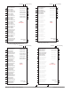
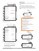
Security Function Block
Overview
Instances - 1 per RME
[LoC;o] Operations Page : 1 to 3
[r;LoC] Read Lock : 1 to 5
[S;LoC] Write Security: 1 to 5
[LoC;P] Profiling Page : 1 to 3
[PAS;E] Password Enable : Off, On
[LoC;L] Locked Access Level : 1 to 5
[roL;L] Rolling Password : Off, On
[PAS;u] User Password : 10 to 999
[PAS;A] Administrator Password : 10 to 999
[CodE] Public Key : xxx
[PASS] Password : xxx
Write Security
Locked Access Level
Rolling Password
User Password
Administrator P
assword
Public Key
Password
Profiling Page
Read Lock
Operations P
age
[`LoC] Lock Menu
[FAct] Factory Page
[ULoC] Unlock Menu
[FAct] Factory Page
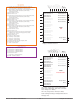
Special Output Function
This function is used to configure outputs when used
with compressors, motorized valves or sequencers.
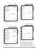
An error (1 - 4), when read, can indicate any of the
following: None, Open, Shorted, Measurement Error,
Bad Cal Data, Ambient Error, RTD Error, Fail, Math
Error, Not Sourced, Stale
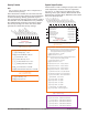
Special Output
Overview
Instances - 4 per RME
[SFn;A] Source Function A : None, Analog Input, Cool Power,
Heat Power, Power, Linearization, Math, Process
Value, Special Function Output 1, Variable
[SFn;b] Source Function B : None, Cool Power, Heat Power,
Power, Linearization, Math, Variable
[`S2;A] Source Zone A : 0 to 16
[`S2;b] Source Zone B : 0 to 16
[Pon;A] Power On Level 1 : -100.0 to 100.0 %
[Pon;b] Power On Level 2 : -100.0 to 100.0 %
[PoF;A] Power Off Level 1 : -100.0 to 100.0 %
[PoF;b] Power Off Level 2 : -100.0 to 100.0 %
[`on;t] Minimum On Time : 0 to 9,999 seconds
[`oF;t] Minimum Off Time : 0 to 9,999 seconds
[``t;t] Valve Travel Time : 10 to 9,999 seconds
[``db] Dead Band : 1.0 to 100.0 %
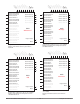
[`o;S1] Output 1 Size : 0 to 9,999
[`o;S2] Output 2 Size : 0 to 9,999
[`o;S3] Output 3 Size : 0 to 9,999
[`o;S4] Output 4 Size : 0 to 9,999
[`t;dL] Time Delay : 0 to 9,999 seconds
[`ot;o] Output Order : Linear, Progressive
[`Si;A] Source Instance A : 1 to 250
[``Fn] Function : Off, Compressor, Motorized Valve, Sequencer
[`Si;b] Source Instance B : 1 to 250
Source Function A
Source Instance A
Source Zone A
Source Error A
Source Function B
Source Instance B
Source Zone B
Source Error B
[`Su;A] Source Value A : -1,999.000 to 9,999.000
[`Su;b] Source Value B : -1,999.000 to 9,999.000
Po
wer On Level 1
Power On Level 2
Power Off Level 1
Power Off Level 2
Minimum On
Time
Minimum Off
Time
Valve Travel Time
Dead Band
Output 1 Size
Output 2 Size
Output 3 Size
Output 4 Size
Time Delay
Output Order
Function
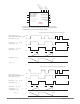
[`o;u1] Output Value 1 : -1,999.000 to 9,999.000 %
[`o;u2] Output Value 2 : -1,999.000 to 9,999.000 %
[`o;u3] Output Value 3 : -1,999.000 to 9,999.000 %
[`o;u4] Output Value 4 : -1,999.000 to 9,999.000 %
[`SoF] Special Output Function Menu
[`SEt] Setup Page
Output Value 4
Output Value 3
Output Value 2
Output Value 1
Error 1 to 4
Source Value A
Source Value B
[`SoF] Special Output Function Menu
[oPEr] Operation Page