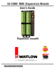
EZ-ZONE RME (Expansion) Module User’s Guide ® Expansion Module TOTAL CUSTOMER SATISFACTION 3 Year Warranty ISO 9001 Registered Company 1241 Bundy Boulevard., Winona, Minnesota USA 55987 Phone: +1 (507) 454-5300, Fax: +1 (507) 452-4507 http://www.watlow.com 0600-0073-0000 Rev. D December 2013 Winona, Minnesota USA Made in the U.S.A.
Safety Information Unit is compliant with European Union directives. See Declaration of Conformity for further details on Directives and Standards used for Compliance. We use note, caution and warning symbols throughout this book to draw your attention to important operational and safety information. A “NOTE” marks a short message to alert you to an important detail. Unit has been reviewed and approved by Factory Mutual as a Temperature Limit Device per FM Class 3545 standard. See: www. fmglobal.
returning any product for credit, repair or evaluation. Make sure the RMA number is on the outside of the carton and on all paperwork returned. Ship on a Freight Prepaid basis. 3. After we receive your return, we will examine it and try to verify the reason for returning it. 4. In cases of manufacturing defect, we will enter a repair order, replacement order or issue credit for material returned.
TC Table of Contents Chapter 1: Overview . . . . . . . . . . . . . . . . . . . . . . . . . . . . . . . . . . . . . 3 A Conceptual View of the RM System . . . . . . . . . . . . . . . . . . . . . . . . . . . 6 Chapter 2: Install and Wire. . . . . . . . . . . . . . . . . . . . . . . . . . . . . . . . 11 Wiring. . . . . . . . . . . . . . . . . . . . . . . . . . . . . . . . . . . . . .
TC Table of Contents (cont.) Chapter 5: Factory Pages. . . . . . . . . . . . . . . . . . . . . . . . . . . . . . . . . 77 Custom Setup Menu. . . . . . . . . . . . . . . . . . . . . . . . . . . . . . . . . . . . . . . . 78 Security Setting Menu . . . . . . . . . . . . . . . . . . . . . . . . . . . . . . . . . . . . . . 78 Security Setting Menu . . . . . . . . . . . . . . . . . . . .
1 Chapter 1: Overview Available EZ-ZONE RM System Literature and Resources Document Title and Part Number Description EZ-ZONE Rail Mount Access (RMA) User's Guide, part number: 0600-0072-0000 Describes how to connect the RM system into an industrial network, how to use data logging, module backup and the real-time clock. EZ-ZONE Rail Mount Controller (RMC) User's Guide, part number: 0600-0070-0000 The RMC module is an advanced integrated controller capable of PID and limit control.
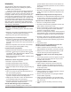
Introduction grated solution that minimizes inter-module connections and potential problems at screw termination points. The EZ-ZONE ® Rail Mount Expansion module (RME) takes the pain out of adding I/O points to your RM system architecture. It just got a whole lot easier to solve the thermal requirements of your system. The RME module is provided in a space-saving, rail-mount package and is highly scalable where you only pay for what you need.
Agency Certifications: UL ® listed, CE, RoHS, W.E.E.E. SEMI F47-0200, Class 1 Div.
A Conceptual View of the RM System The flexibility of the RM system software and hardware allows for a large range of configurations. Focusing on the RME module, acquiring a better understanding of its overall functionality and capabilities while at the same time planning out how this module can be used will deliver maximum effectiveness in your application.
that instance alone that will be reset. RMC module - The logic block (within the RME module) is configured as an OR function - The RME output function is tied to the internal output of the logical OR function Note: Alarms will reset automatically when the condition that caused the alarm goes back to a non-alarm state if the alarm latching prompt is set to non-latching (Setup Page, Alarm Menu).
A Conceptual View of RM Hardware Configurations Due to the scalability and flexibility in the system components a user has several options available in the way that the hardware can be connected. Listed below are a few examples. RM System Connected to a Remote User Interface (RUI) and a PC In this configuration the RUI and PC are connected to the RM system via Watlow's Standard Bus where both will be able to talk directly to any interconnected system module.
Module Orientation The picture below represents one of six possible RM modules. All six will have four slots on the face (slot A, B, D, and E) and one on the bottom (slot C) not shown. All of these slots are not always used on all modules. On the face of the module there is a button (white circle) under the Zone address (5) that when pushed and held has the following functions: 1.For any module, push and hold for ~ 2 seconds. The address will intensify indicating that it can now be changed.
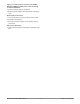
EZ-ZONE RM-Expansion Module - System Diagram with up to 24 Inputs/Outputs Input Function Input Device Digital Input (or output) 1 - 6 Switch contact or volts dc 3 - Universal/Retransmit or 4 - 2A SSR or 2 - 10A SSR Output 1 - 6 or 4 - 5A Mechanical Relays None, Process, Switched dc/Open collector, 5A Mechanical Relay - Form A, or 10A SSR - Form A, 2A SSR - Form A 6 Digital I/O Slot A Input Device Digital Input (or output) 7 - 12 Switch contact or volts dc Output Function Off, Heat, Cool, Alarm, Event
2 Chapter 2: Install and Wire Dimensions As can be seen below the dimensions of the RME modules will change slightly based on the type of connector used. Module Removal Clearance Standard Connectors 147.07 mm ( 5.8 in ) 75.08 mm ( 3.0 in ) 44.45 mm ( 1.75 in ) 101.60 mm ( 4.00 in ) 116.08 mm ( 4.57 in ) 15° 51.56 mm ( 2.03 in ) Latch in open position 165 mm ( 6.50 in ) Module Removal Displacement Module Removal Clearance Straight Connectors 155 mm ( 6.10 in ) 75.08 mm ( 3.0 in ) 44.
Dimensions Module Removal Clearance Ring Terminal Connectors 164.9 mm ( 6.5 in ) 80.54 mm ( 3.17 in ) 44.45 mm ( 1.75 in ) 101.60 mm ( 4.00 in ) 116.08 mm ( 4.57 in ) 15° 184.58 mm ( 7.27 in ) 51.56 mm ( 2.03 in ) Module Removal Displacement Chassis Mount Front View (Module Removed) - Screw Connection Pattern 58.67 mm (2.31 in) 17.53 mm (0.69 in) 51.56 mm (2.03 in) 32.77 mm (1.29 in) 60.45 mm (2.38 in) 35.81 mm (1.41 in) 35.05 mm (1.38 in) 16.76 mm (0.
Power Supplies DSP60 DSP30 55.6 mm 2.189 in ++ - - L DC OK DSP60 N L N 5 6 6 14.20 mm 0.559 in 14.20 mm 0.559 in 5 Power Supply Specifications DSP100 DSP 30 56.8 mm 2.236 in 89.9 mm 3.539 in 49.00 mm 1.929 in 12 3 4 vout ADJ. 32.10 mm 1.264 in DC LO L 5 N 6 14.20 mm 0.559 in 5 43.1 mm 1.697 in DSP100 91.00 mm 3.583 in DC OK 9.75 mm 0.384 in 91.00 mm 3.583 in ++ - - 32.10 mm 1.264 in DC LO 91.00 mm 3.583 in 9.75 mm 0.384 in DSP30 1.697 in DC OK vout ADJ. 91.00 mm 3.
RME Installation and Removal on a DIN Rail Modular Backplane Connector The picture on the right shows the Modular Backplane Connector, both front and rear view. The rear view is bringing in to focus a metal clip. If the DIN rail is grounded the Modular Backplane Connector and the module connected to it will be also (recommended).
Module Removal To remove a module from the Modular Backplane Connector find the red tab protruding from the bottom of the module and pull back on it as shown to the right. While pulling back on the red tab the two mounting posts will release the module where the module can then be lifted up and out of the Modular Backplane Connector.
Wiring Expansion Module (RME x - x x x x - x x x x) Slot A Slot B Slot D Slot E Terminal Function Inputs Configuration Digital Inputs 1-6 7 - 12 13 - 18 19 - 24 B1 D1 D2 D3 D4 D5 D6 Z1 B7 D7 D8 D9 D10 D11 D12 Z7 B13 D13 D14 D15 D16 D17 D18 Z13 B19 D19 D20 D21 D22 D23 D24 Z19 --- --- --- 13 - 16 - - - Common dc+ input dc+ input dc+ input dc+ input dc+ input dc+ input Internal Supply 6 Digital Inputs Part # Digits 5, 6, 7, 8 Slot A: RME _ - [C] _ _ _ - _ _ _ _ Slot B: RME _ - _ [C] _ _
Expansion Module (RME x - x x x x - x x x x) Slot A Slot B Slot D Slot E Terminal Function 1-2 L1 L1 K1 K1 L2 L2 K2 K2 --- - - 13 - 14 L13 L13 K13 K13 L14 L14 K14 K14 Configuration 2, 10A Form A SSR Outputs Outputs (cont.
All Modules - Front View Standard Connector Slot D Slot E Slot A Slot B Slot C 98 99 power Watlow EZ-ZONE ® RME Module • 18 • Chapter 2 Install and Wire
RME System Isolation Blocks Mechanical Relay, Solid-State Relay, Outputs Digital Inputs & Outputs No Isolation Switched DC, Open Collector, Process outputs Low-voltage Isolation Communications Ports Safety Isolation Safety Isolation Controller Power Supply 20.4 to 30.8VÎ (dc) 20.4 to 30.
Warning: ç Use National Electric (NEC) or other country-specific standard wiring and safety practices when wiring and connecting this controller to a power source and to electrical sensors or peripheral devices. Failure to do so may result in damage to equipment and property, and/or injury or loss of life. • 20.4 to 30.
Warning: ç Digital Inputs 1 to 24 RME Part # Digit 5, 6, 7, 8 is C Use National Electric (NEC) or other country-specific standard wiring and safety practices when wiring and connecting this controller to a power source and to electrical sensors or peripheral devices. Failure to do so may result in damage to equipment and property, and/or injury or loss of life. Slot A, B, D, E Common DC Input DC Input Note: Maximum wire size termination and torque rating: • 0.0507 to 3.
Warning: ç Digital Output (1 to 24) Wiring Example - Switched DC to DIN-A-MITE® Collector Outputs Common Use National Electric (NEC) or other country-specific standard wiring and safety practices when wiring and connecting this controller to a power source and to electrical sensors or peripheral devices. Failure to do so may result in damage to equipment and property, and/or injury or loss of life. B_ D_ D_ Note: Htr 1 Htr 2 D_ Maximum wire size termination and torque rating: • 0.0507 to 3.
Warning: ç Quencharc Wiring Example In this example the Quencharc circuit (Watlow part# 0804-0147-0000) is used to protect the RME internal circuitry from the counter electromagnetic force from the inductive user load when de-engergized. It is recommended that this or an equivalent Quencharc be used when connecting inductive loads to the RME outputs.
Warning: ç Quad 2A SSR Outputs 1-4, 7-10, 13-16, 19 - 22 RME Part # Digit 5, 6, 7, 8 is L Use National Electric (NEC) or other country-specific standard wiring and safety practices when wiring and connecting this controller to a power source and to electrical sensors or peripheral devices. Failure to do so may result in damage to equipment and property, and/or injury or loss of life. Slot D, E L_ K_ L_ Note: Maximum wire size termination and torque rating: • 0.0507 to 3.
Warning: ç Standard Bus EIA-485 Communications • Wire T-/R- to the A terminal of the EIA-485 port. • Wire T+/R+ to the B terminal of the EIA-485 port. • Wire common to the common terminal of the EIA-485 port. • Do not route network wires with power wires. Connect network wires in daisy-chain fashion when connecting multiple devices in a network.
Warning: occur. ç Use National Electric (NEC) or other country-specific standard wiring and safety practices when wiring and connecting this controller to a power source and to electrical sensors or peripheral devices. Failure to do so may result in damage to equipment and property, and/or injury or loss of life. Note: Maximum wire size termination and torque rating: • 0.0507 to 3.30 mm2 (30 to 12 AWG) single-wire termination or two 1.31 mm2 (16 AWG) • 0.8 Nm (7.0 in-lb.
Connecting and Wiring the Modules RM System Connections taining to the split rail system diagram shown below. The power supply used is the 91W supply. The top DIN rail now has the following modules: Components of a RM system can be installed as stand-alone modules or can be interconnected on the DIN rail as shown below. When modules are connected together, power and communications are shared between modules over the modular backplane interconnection.
Wiring a Serial EIA-485 Network 120 Ω resistor across T+/R+ and T-/R- of the last controller on a on a network. Do not route network wires with power wires. Connect network wires in daisy-chain fashion when connecting multiple devices in a network. A termination resistor may be required. Place a Note: Termination resistors when used, require a termination resistor at both ends of the network. A network using Watlow's Standard Bus and an RUI/Gateway.
Conventions Used in the Menu Pages Display To better understand the menu pages that follow review the naming conventions used. When encountered throughout this document, the word "default" implies as shipped from the factory.
3 Chapter 3: Operations Pages Operation Page Parameters To navigate to the Operations Page using the RUI, follow the steps below: 1. From the Home Page, press both the Up ¿ and Down ¯ keys for three seconds. [``Ai] will appear in the upper display and [oPEr] will appear in the lower display. 2. Press the Up ¿ or Down ¯ key to view available menus. the Up ¿ or Down ¯ key to select and then press the Advance Key ‰ to enter. 5. Press the Up ¿ or Down ¯ key to move through available menu prompts. 6.
RME Module Parameter Name Description Display Range • Operations Page Default Modbus Relative Address CIP Class Profibus Instance Index Attribute hex (dec) Parameter ID Data Type & Read/ Write [`dio] [oPEr] Digital Input / Output Menu [`do;S] [ do.S] Digital Output (1 to 24) Output State View the state of this output. [`off] Off (62) [``on] On (63) ---- 372 [off 30] 0x6A (106) 1 to 18 (24) 7 28 6007 uint R [`di;S] [ di.
Display RME Module Parameter Name Description Range • Operations Page Default Modbus Relative Address CIP Class Profibus Instance Index Attribute hex (dec) Parameter ID Data Type & Read/ Write [A;sir] [A.Sir] Alarm (1 to 4) Alarm Silence Request Write to this register to silence an alarm 0 None 1466 [offset 60] 0x6D (109) 1 to 8 0xE (14) 15 9014 uint W [`a;st] [ A.
Display RME Module Parameter Name Description Range • Operations Page Default Modbus Relative Address CIP Class Profibus Instance Index Attribute hex (dec) Parameter ID Data Type & Read/ Write No Display Current (1 to 4) Actual Power Power delivered to output monitored by CT. 0.0 to 100.
RME Module Parameter Name Description Display No Display Compare (1 to 8) Error Read reported cause for compare error • Operations Page Modbus Relative Address Range Default None (61) Open (65) Shorted (127) Measurement error (140) Bad Cal Data (139) Ambient Error (9) RTD Error (141) Fail (32) Math Error (1423) Not Sourced (246) Stale (1617) ---- 4004 [offset 40] CIP Class Profibus Instance Index Attribute hex (dec) Parameter ID Data Type & Read/ Write 0x80 (128) 1 to 8 0x0D (13) ----
RME Module Parameter Name Description Display Range • Operations Page Default Modbus Relative Address CIP Class Profibus Instance Index Attribute hex (dec) Parameter ID Data Type & Read/ Write [`Su;A] [ Su.A] Counter (1 to 8) Source Value A View the value of Source A. [`off] Off (62) [``on] On (63) ---- 4472 [off 40] 0x82 (130) 1 to 8 7 ---- 30007 uint R [`Su;b] [ Su.b] Counter (1 to 8) Source Value B View the value of Source B.
RME Module Parameter Name Description Display Range • Operations Page Default Modbus Relative Address CIP Class Profibus Instance Index Attribute hex (dec) Parameter ID Data Type & Read/ Write [`Su;g] [ Su.g] Logic (1 to 8) Source Value G View the value of Source G. [`off] Off (62) [``on] On (63) ---- 3080 [off 80] 0x7F (127) 1 to 8 0x1F (31) ---- 27031 uint R [`Su;h] [ Su.h] Logic (1 to 8) Source Value H View the value of Source H.
Display RME Module Parameter Name Description • Operations Page Range Default Modbus Relative Address CIP Class Profibus Instance Index Attribute hex (dec) Parameter ID Data Type & Read/ Write [``o;u] [ o.v] Math (1 to 8) Output Value View the value of this function's output. -1,999.000 to 9,999.000°F or units -1,128.000 to 5,537.000°C ---- 2222 [off 70] 0x7D (125) 1 to 8 0x16 (22) ---- 25022 float R No Display Math (1 to 8) Error Read reported cause for math error.
Display RME Module Parameter Name Description • Operations Page Range Default Modbus Relative Address No Display Special Output Function (1 to 4) Error 2 Read reported cause for output error. None (61) Open (65) Shorted (127) Measurement error (140) Bad calibration data (139) Ambient error (9) RTD error (14) Fail (32) Math error (1423) Not sourced (246) Stale (1617) Can't process (1659) ---- 6644 [offset 80] [`o;u3] [ o.
4 Chapter 4: Setup Pages Setup Page Parameters To navigate to the Setup Page using the RUI, follow the steps below: 1. From the Home Page, press both the Up ¿ and Down ¯ keys for six seconds. [``Ai] will appear in the upper display and [`Set] will appear in the lower display. Note: If keys are released when [OPEr] is displayed, press the Infinity Key ˆ or reset key to exit and repeat until [`Set] is displayed. 4.
[`op;8] [`ip;9] [`op;9] [ip;10] [op;10] Output Point 8 Input Point 9 Output Point 9 Input Point 10 Output Point 10 [`CPE] [`Set] Compare Menu [```1] [`CPE] Compare (1 to 8) [``Fn] Function [`toL] Tolerance [SFn;A] Source Function A [`Si;A] Source Instance A [`S2;A] Source Zone A [SFn;B] Source Function B [`Si;b] Source Instance B [`S2;b] Source Zone B [`Er;h] Error Handling [tMr] [`Set] Timer Menu [```1] [tMr] Timer (1 to 8) [``Fn] Function [SFn;A] Sourc
RME Module Display Parameter Name Description Range • Setup Page Default Modbus Relative Address CIP Class Profibus Instance Index Attribute hex (dec) Parameter ID Data Type & Read/ Write [`dio] [`Set] Digital Input / Output Menu [`dir] [ dir] Digital Input/Output (1 Output [OtPt] Output (68) to 24) [``in] Input Voltage (193) Direction [iCon] Input Dry Contact Set this function to operate (44) as an input or output.
RME Module Display Parameter Name Description Range • Setup Page Default Modbus Relative Address CIP Class Profibus Instance Index Attribute hex (dec) Parameter ID Data Type & Read/ Write [``Fi] [ Fi] Digital Output (1 to 24) Function Instance Set the instance of the function selected above. 1 to 24 1 370 [offset 30] 0x6A (106) 1 to (24) 6 84 6006 uint RWES [``s2] [ SZ] Digital Output (1 to 24) 0 to 16 Source Zone Set the zone of the function selected above.
RME Module Display Parameter Name Description Range • Setup Page Default Modbus Relative Address CIP Class Profibus Instance Index Attribute hex (dec) Parameter ID Data Type & Read/ Write None 1290 [offset 20] 0x6E (110) 1 to 8 6 ---- 10006 uint RWES 1 1282 [offset 20] 0x6E (110) 1 to 8 2 ---- 10002 uint RWES Action (1 to 8) 0 to 16 Source Zone A Set the zone of the function selected above.
RME Module Display Parameter Name Description • Setup Page Range Default ---- Modbus Relative Address CIP Class Profibus Instance Index Attribute hex (dec) Parameter ID Data Type & Read/ Write [otpt] [`Set] Output Menu [``Fn] [ Fn] Output Digital (1 to 4, 7 to 10, 13 to 16, 19 to 22) Function Select what function will drive this output.
RME Module Display Parameter Name Description Range • Setup Page Default Parameter ID Data Type & Read/ Write 0x6A (106) 1 to (24) 0x0C (12) ---- 6012 uint RWES Output Digital (1 to 4, 7 to [`Ftb] Fixed Time Base Fixed 10, 13 to 16, 19 to 22) Time (34) Control Base [`utb] Variable Time Base Set the output control type. (103) This parameter is only used with PID control, but can be set anytime. 362 [offset 30] 0x6A (106) 1 to (24) 2 ---- 6002 uint RWES [`o;tb] [ o.
RME Module Display Parameter Name Description Range • Setup Page Default Modbus Relative Address CIP Class Profibus Instance Index Attribute hex (dec) Parameter ID Data Type & Read/ Write [``Fn] [ Fn] Output Process (1 to 3, 7 to 9, 13 to 15, 19 to 21) Function ** Set the type of function that will drive this output.
RME Module Display Parameter Name Description Range • Setup Page Default Modbus Relative Address CIP Class Profibus Instance Index Attribute hex (dec) Parameter ID Data Type & Read/ Write [`S;hi] [ S.hi] Output Process (1 to 3, 7 to -100.0 to 100.0 9, 13 to 15, 19 to 21) Scale High ** Set the scale high for process output in electrical units. This value, in volts or milliamps, will correspond to 100% PID power output or range high value. 10.
RME Module Display Parameter Name Description Range • Setup Page Default Modbus Relative Address CIP Class Profibus Instance Index Attribute hex (dec) Parameter ID Data Type & Read/ Write [`s2;A] [ SZ.A] Alarm (1 to 8) 0 or 16 Source Zone Set the zone of the function selected above. 0 1488 [offset 60] 0x6D (109) 1 to 8 0x19 (25) ---- 9025 uint RWES [`A;hy] [ A.hy] Alarm (1 to 8) 0.001 to 9,999.000°F or Hysteresis units Set the hysteresis for an 0.001 to 5,555.000°C alarm.
RME Module Display Parameter Name Description Range • Setup Page Default Modbus Relative Address CIP Class Profibus Instance Index Attribute hex (dec) Parameter ID Data Type & Read/ Write [`A;Si] [ A.Si] Alarm (1 to 8) [`oFF] Off (62) Silencing [``on] On (63) Turn alarm silencing on to allow the user to disable this alarm. Off 1450 [offset 60] 0x6D (109) 1 to 8 6 11 9006 uint RWES [A;dSP] [A.dSP] Alarm (1 to 8) Display Display an alarm message when an alarm is active.
RME Module Display Parameter Name Description Range • Setup Page Default Modbus Relative Address CIP Class Profibus Instance Index Attribute hex (dec) Parameter ID Data Type & Read/ Write [`C;SC] [ C.SC] Current (1 to 4) 0 to 9,999.000 Scaling Use Input Current Scaling to adjust scaling to match the transformer's high range, in amperes. 50.0 1122 [offset 50] 0x73 (115) 1 to 4 0x16 (22) 148 15022 float RWES [C;;oFs] [C.oFS] Current (1 to 4) -9,999.000 to 9,999.
RME Module Display Parameter Name Description Range • Setup Page Default Modbus Relative Address CIP Class Profibus Instance Index Attribute hex (dec) Parameter ID Data Type & Read/ Write [`iP;2] [ ip.2] Linearization (1 to 8) Input Point 2 Set the value that will be mapped to output 2. -1,999.000 to 9,999.000 1.0 5556 [offset 70] 0x86 (134) 1 to 8 9 159 34009 float RWES [`oP;2] [ op.2] Linearization (1 to 8) Output Point 2 Set the value that will be mapped to input 2. -1,999.
RME Module Display Parameter Name Description Range • Setup Page Default Modbus Relative Address CIP Class Profibus Instance Index Attribute hex (dec) Parameter ID Data Type & Read/ Write [`iP;8] [ ip.8] Linearization (1 to 8) Input Point 8 Set the value that will be mapped to output 8. -1,999.000 to 9,999.000 7.0 5568 [offset 70] 0x86 (134) 1 to 8 0x0F (15) 171 34015 float RWES [`oP;8] [ op.8] Linearization (1 to 8) Output Point 8 Set the value that will be mapped to input 8.
RME Module Display Parameter Name Description Range • Setup Page Default Modbus Relative Address CIP Class Profibus Instance Index Attribute hex (dec) Parameter ID Data Type & Read/ Write [sfn;;A] [SFn.A] Compare (1 to 8) Source Function A Set the type of function that will be used for this source.
RME Module Display [`Er;h] [ Er.h] Parameter Name Description Compare (1 to 8) Error Handling Use Error Handling to select the output value and error output state of this function if it receives an error signal from one or more sources and it cannot determine the output value.
RME Module Display Parameter Name Description Range • Setup Page Default Modbus Relative Address CIP Class Profibus Instance Index Attribute hex (dec) Parameter ID Data Type & Read/ Write [sfn;A] [SFn.A] Timer (1 to 8) Source Function A Set the type of function that will be used for this source which is the timer run signal.
RME Module Display Parameter Name Description Range • Setup Page Default Modbus Relative Address CIP Class Profibus Instance Index Attribute hex (dec) Parameter ID Data Type & Read/ Write [sfn;B] [SFn.b] Timer (1 to 8) Source Function B Set the type of function that will be used to reset a retentive timer which is the timer reset signal.
RME Module Display [`LEu] [ LEv] Parameter Name Description Range • Setup Page Default Timer (1 to 8) [high] High (37) Active Level [LoW] Low (53) Set which output state will indicate on.
RME Module Display Parameter Name Description [sas;A] Counter (1 to 8) [SAS.A] State Active Source A Set what output state will indicate on. Range • Setup Page Default [both] Both (130 [high] High (37) [LoW] Low (53) Modbus Relative Address CIP Class Profibus Instance Index Attribute hex (dec) Parameter ID Data Type & Read/ Write High 4480 [offset 40] 0x82 (130) 1 to 4 0xB (11) ---- 30011 uint RWES [sfn;B] [SFn.
RME Module Display Parameter Name Description Range [trgt] [trgt] Counter (1 to 8) 0 to 9,999 Target Value Set the value that will turn the output value on. [`lAt] [ LAt] Counter (1 to 8) Latching Output latched.
RME Module Display Parameter Name Description Range • Setup Page Default Modbus Relative Address CIP Class Profibus Instance Index Attribute hex (dec) Parameter ID Data Type & Read/ Write [sfn;A] [SFn.A] Logic (1 to 8) Source Function A Set the type of function that will be used for this source.
RME Module Display Parameter Name Description Range • Setup Page Default Modbus Relative Address CIP Class Profibus Instance Index Attribute hex (dec) Parameter ID Data Type & Read/ Write [sfn;B] [SFn.b] Logic (1 to 8) Source Function B Set the type of function that will be used for this source.
RME Module Display Parameter Name Description Range • Setup Page Default Modbus Relative Address CIP Class Profibus Instance Index Attribute hex (dec) Parameter ID Data Type & Read/ Write [sfn;C] [SFn.C] Logic (1 to 8) Source Function C Set the type of function that will be used for this source.
RME Module Display Parameter Name Description Range • Setup Page Default Modbus Relative Address CIP Class Profibus Instance Index Attribute hex (dec) Parameter ID Data Type & Read/ Write [sfn;D] [SFn.d] Logic (1 to 8) Source D Set the type of function that will be used for this source.
RME Module Display Parameter Name Description Range • Setup Page Default Modbus Relative Address CIP Class Profibus Instance Index Attribute hex (dec) Parameter ID Data Type & Read/ Write [sfn;E] [SFn.E] Logic (1 to 8) Source E Function Set the type of function that will be used for this source.
RME Module Display Parameter Name Description Range • Setup Page Default Modbus Relative Address CIP Class Profibus Instance Index Attribute hex (dec) Parameter ID Data Type & Read/ Write [sfn;F] [SFn.F] Logic (1 to 8) Source Function F Set the type of function that will be used for this source.
RME Module Display Parameter Name Description Range • Setup Page Default Modbus Relative Address CIP Class Profibus Instance Index Attribute hex (dec) Parameter ID Data Type & Read/ Write [sfn;g] [SFn.g] Logic (1 to 8) Source Function G Set the type of function that will be used for this source.
RME Module Display Parameter Name Description Range • Setup Page Default Modbus Relative Address CIP Class Profibus Instance Index Attribute hex (dec) Parameter ID Data Type & Read/ Write [sfn;h] [SFn.h] Logic (1 to 8) Source Function H Set the type of function that will be used for this source.
RME Module Display Parameter Name Description Range • Setup Page Default Modbus Relative Address CIP Class Profibus Instance Index Attribute hex (dec) Parameter ID Data Type & Read/ Write [MAt] [`Set] Math Menu [``Fn] [ Fn] Math (1 to 8) Function Set the operator that will be applied to the sources.
RME Module Display Parameter Name Description Range • Setup Page Default Modbus Relative Address CIP Class Profibus Instance Index Attribute hex (dec) Parameter ID Data Type & Read/ Write [sfn;B] [SFn.b] Math (1 to 8) Source Function B Set the type of function that will be used for this source.
RME Module Display Parameter Name Description Range • Setup Page Default Modbus Relative Address CIP Class Profibus Instance Index Attribute hex (dec) Parameter ID Data Type & Read/ Write 2186 [offset 70] 0x7D (125) 1 to 8 4 ---- 25004 uint RWES 1 2196 [offset 70] 0x7D (125) 1 to 8 9 ---- 25009 uint RWES Math (1 to 8) 0 to 16 Source Zone D Set the zone of the function selected above.
RME Module Display Parameter Name Description Range • Setup Page Default 1 to 250 Modbus Relative Address CIP Class Profibus Instance Index Attribute hex (dec) Parameter ID Data Type & Read/ Write 1 2198 [offset 70] 0x7D (125) 1 to 8 0x0A (10) ---- 25010 uint RWES 0 2208 [offset 70] 0x7D (125) 1 to 8 0x0F (15) ---- 25015 uint RWES -1,999.000 to 9,999.000 0.0 2226 [offset 70] 0x7D (125) 1 to 8 0x18 (24) 129 25024 float RWES -1,999.000 to 9,999.000 1.
RME Module Display Parameter Name Description Range • Setup Page Default Modbus Relative Address CIP Class Profibus Instance Index Attribute hex (dec) Parameter ID Data Type & Read/ Write [a;unt] [A.unt] Math (1 to 8) Altitude Units If Math function is set for Pressure to Altitude units, set units of measure for conversion.
RME Module Display Parameter Name Description Range • Setup Page Default Modbus Relative Address CIP Class Profibus Instance Index Attribute hex (dec) Parameter ID Data Type & Read/ Write [sfn;B] [SFn.B] Special Output (1 to 4) Source Function B Set the type of function that will be used for this source.
RME Module Display Parameter Name Description Range • Setup Page Default Modbus Relative Address CIP Class Profibus Instance Index Attribute hex (dec) Parameter ID Data Type & Read/ Write [`on;t] [ on.t] Special Output (1 to 4) On Time If Function is set to Compressor Control: • Set Minimum On Time and Minimum Off Time to the minimum span of time, in seconds, that the compressor will be on or off.
RME Module Display Parameter Name Description Range • Setup Page Default Modbus Relative Address CIP Class Profibus Instance Index Attribute hex (dec) Parameter ID Data Type & Read/ Write [`o;S2] [ o.S2] Special Output (1 to 8) 0 to 9,999 Output 2 Size If Function is set to Sequencer: • Set the size of outputs 2 through 4 to represent a percentage of the total output capacity. Outputs 2 through 4 will control using the ON-OFF algorithm.
RME Module Display Parameter Name Description Range • Setup Page Default Modbus Relative Address CIP Class Profibus Instance Index Attribute hex (dec) Parameter ID Data Type & Read/ Write [`uAr] [`Set] Variable Menu [tyPE] [tyPE] Variable 1 to 8 Data Type Set the variable's data type. [AnLg] Analog (1215) [`Dig] Digital (1220) Analog 6380 [offset 20] 0x66 (102) 1 to 8 1 210 2001 uint RWES [Unit] [Unit] Variable 1 to 8 Units Set the variable's units.
5 Chapter 5: Factory Pages Factory Page Parameters To navigate to the Factory Page using the RUI, follow the steps below: 5. Press the Up ¿ or Down ¯ key to move through available menu prompts. 1. From the Home Page, press and hold both the Advance ‰ and Infinity ˆ keys for six seconds. 6. Press the Infinity Key ˆ to move backwards through the levels: parameter to submenu; submenu to menu; menu to Home Page. 2. Press the Up ¿ or Down ¯ key to view available menus. 7.
Display Expansion Module Parameter Name Description • Factory Page Range Default [nonE] None (61) [`C_F] Display Units (156) [USr;r] User Restore Set (227) [`A;Lo] Alarm Low Set Point (42) [`A;hi] Alarm High Set Point (78) [`A;hy] Alarm Hysteresis (97) [CU;st] Custom (180) 1 = None 2 = Display Units 3 = Alarm Low Set Point 4 = Alarm High Set Point 5 to 20 = None Modbus Relative Address CIP Class Profibus Instance Index Attribute hex (dec) Parameter ID Data Type & Read/ Write [CUSt] [FCty]
Display Expansion Module Parameter Name Description • Range Factory Page Default Modbus Relative Address CIP Class Profibus Instance Index Attribute hex (dec) Parameter ID Data Type & Read/ Write [rLoC] [rLoC] Security Setting Read Lock Set the read security clearance level. The user can access the selected level and all lower levels. Applies regardless of Password Enable setting. Set the Read Lock clearance level. The user can have read access to the selected level and all lower levels.
Display [pas;a] [PAS.A] Expansion Module Parameter Name Description Security Setting Administrator Password Applies if Password Enable is ON. Used to acquire access to menus made available through the Locked Access Level setting. Do not forget the password as it is required to change Locked Access Level, Read Lock, Write Security and the ability to change the Passwords.
6 Chapter 6: Features Saving and Restoring User Settings. . . . . . . . . . . . . . . . . . . . . . . . . . 82 Inputs . . . . . . . . . . . . . . . . . . . . . . . . . . . . . . . . . . . . . . . . . . . . . . 82 Outputs . . . . . . . . . . . . . . . . . . . . . . . . . . . . . . . . . . . . . . . . . . . . . 82 Variable Time Base. . . . . . . . . . . . . . . . . . . . . .
Saving and Restoring User Settings Temperature Input Point 10 Recording setup and operations parameter settings for future reference is very important. If you unintentionally change these, you will need to program the correct settings back into the controller to return the equipment to operational condition. After you program the controller and verify proper operation, use User Settings Save [USr;S] (Setup Page, Global Menu) to save the settings into either of two files in a special section of memory.
switches the compressor on and off. The compressor will not turn on until the output power exceeds the Compressor On % Power for a time longer than the Compressor On Delay. The compressor will not turn off until the output power exceeds the Compressor Off % Power for a time longer than the Compressor Off Delay.
Process Alarms A process alarm uses one or two absolute set points to define an alarm condition. Select the alarm type [`A;ty] via the Setup Page, Alarm Menu. Alarm Set Points The alarm high set point defines the process value or temperature that will trigger a high side alarm. The alarm low set point defines the temperature that will trigger a low side alarm. For deviation alarms, a negative set point represents a value below closed loop set point.
Alarm Blocking Alarm blocking allows a system to warm up after it has been started up. With alarm blocking on, an alarm is not triggered when the process temperature is initially lower than the alarm low set point or higher than the alarm high set point. The process temperature has to enter the normal operating range beyond the hysteresis zone to activate the alarm function.
The following examples show how the Lockout Menu parameters may be used in applications: 1. You can lock out access to the Operations Page but allow an operator access to the Profile Menu, by changing the default Profile Page and Operations Page security levels. Change Lock Operations Page [LoC;o] to 3. If Set Lockout Security [SLoC] is set to 2 or higher and the Read Lockout Security [rLoC] is set to 2, the Home Pages can be accessed, and all writable parameters can be written to.
push the Advance key ‰ to proceed to the Password [ pass] prompt. If not find your way back to the Factory Page as described above. 4. Execute the calculation defined below (7b or 8b) for either the User or Administrator. 5. Enter the result of the calculation in the upper display play by using the Up ¿ and Down ¯ arrow keys or use EZ-ZONE Confgurator Software. 6. Exit the Factory Page by pushing and holding the Infinity ˆ key for two seconds.
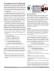
Software Configuration use. Using EZ-ZONE® Configurator Software To enable a user to configure the RME module using a personal computer (PC), Watlow has provided free software for your use. If you have not yet obtained a copy of this software insert the CD (Controller Support Tools) into your CD drive and install the software.
In the previous screen shot the RME is shown highlighted to bring greater clarity to the control in focus. Any EZ-ZONE device on the network will appear in this window and would be available for the purpose of configuration or monitoring. After clicking on the control of choice simply click the next button once again. The next screen appears below. as an input, output parameters do not apply and are therefore grayed out.
ting without understanding the impact it would be easy and perhaps faster to download a saved configuration back to the control versus trying to figure out what was changed. Of course, there is an option to exit without saving a copy to the local hard drive. After selecting Save above click the "Finish" button once again. The screen below will than appear. When saving the configuration note the location where the file will be placed (Saved in) and enter the file name (File name) as well.
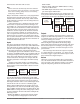
Function Block Descriptions Alarm Function Each of the next several pages graphically shows each of the RME function blocks. Note that as you view each you will find text that is black and text that appears gray. The gray text represents inputs that are not currently available based on the functions defined use (red text). For instance, when the defined use of the Alarm function is set to Off, all parameters will appear gray.
A A A Al Ala larm larm arm larm Ala Ala Al Al S H r A a a C i L r Ala m H Ala Ala rm L rm B rm S larmm De ow S igh S lence lear rm yst rm rm atc loc ilen Di lay et et Re Re Ty eres Log Sid hin kin cin spl Tim Poi Poi que que pe is ic es g g g ay e nt nt st st Alarm Source Alarm Source Instance Alarm Source Zone Alarm Source Error Er ror Fu Tol Han nc era dl tio nc in g n e Source Function A Source Instance A Source Zone A Source Error A Alarm State Alarm Latched Source Value A Source Value B Compare O
Er ror Fu Tol Han nc era dli tio nc ng n e Source Function A Source Instance A Source Zone A Source Error A Er ro Fu To r Ha nc ler n tio an dlin n ce g Source Function A Source Instance A Source Zone A Source Error A Source Value A Source Value B Compare Not Equal To Compare Greater Than Source Function B Source Instance B Source Zone B Source Error B Source Value A Source Value B Source Function B Source Instance B Source Zone B Source Error B Output Value Error Output Value Error A not equal
Counter Function [`Ctr] Counter Menu [`SEt] Operation Page Function counts up or down from Load Value and produces Output Value = On when Count = Target Value. [`Cnt] Count : 0 to 9,999 [`Su;A] Source Value A : Off, On Note: Count value clears on power loss. [`Su;b] Source Value B : Off, On [``o;u] Output Value : Off, On Load Value restored on power up. Counter Operation: Whenever a prescribed clock transition occurs without an error on source B the count will be equal to the Load Value.
Digital Input/Output Function Global Function Note: This function allows the user to change display units as well as save and restore user settings. Input value is passed to any specified digital input source when programmed as input by that function block. U AC Us ser e S Di Line Dis r Se etti spl Fr pl tti ng ay eq ay ngs s R Un uen Pla Sa est its cy irs ve ore Output value determine by Function Block driving this output.
[`LgC] Logic Menu [`SEt] Setup Page [`Lnr] Linearization Menu [oPEr] Operation Page [`Su;A] Source Value A : -1,999.000 to 9,999.000 [``Fn] Function : Off, AND, OR, Equal To, NAND, NOR, Not Equal To, Latch, RS Flip Flop [SFn;A] Source Function A : None, Alarm, Compare, Counter, Digital I/O, Profile Event Out A to H, Function Key, Limit, Logic, Special Function Output 1 to 4, Timer, Variable [oFSt] Offset : -1,999.000 to 9,999.000 [``o;u] Output Value : -1,999.000 to 9,999.
Function Source Function A Source Instance A Source Zone A Source Error A Function Error Handling Source Function A Source Instance A Source Zone A Source Error A Source Value A Source Value B Source Value C Source Function B Source Instance B Source Zone B Source Error B Source Value D Source Function C Source Instance C Source Zone C Source Error C Source Value G Source Value H Source Function D Source Instance D Source Zone D Source Error D Logic AND Source Value E Source Value F Source Functi
Function Source Function A Source Instance A Source Zone A Source Error A Source Function B Source Instance B Source Zone B Source Error B Source Function C Source Instance C Source Zone C Source Error C Source Function D Source Instance D Source Zone D Source Error D Function Error Handling Source Function A Source Instance A Source Zone A Source Error A Source Value A Source Value B Source Value C Source Value D Source Value E Source Value F Source Value G Source Value H Output Value Error Function
Function Source Function A Source Instance A Source Zone A Source Error A The Math function block accepts multiple inputs and performs a programmed math function to derive an output value with Filter and Offset values applied. It is assumed that no input error conditions apply. Some math operations must be performed in the user's units.
P A R res lt Fu Scal Scal Rang ange sure itude nc e L e H e L H U U Fi Of tio n n l n ow igh ow igh its its ter fset [MAt] Math Menu [`SEt] Setup Page [``Fn] Function : Off, Average, Process Scale, Deviation Scale, Switch Over, Differential, Ratio, Add, Multiply, Absolute Difference, Minimum, Maximum, Square Root, Sample and Hold, Pressure to Altitude, Dewpoint [SFn;A] Source Function A : None, Analog Input, Current, Cool Power, Heat Power, Power, Linearization, Math, Process Value, Set Point Closed, Set P
P A R res lt Fu Scal Scal Rang ange sure itude nc e L e H e L H U U Fi Of tio n n l n ow igh ow igh its its ter fset P A R res lt Fu Sca Scal Rang ange sure itude nc le L e H e L H U U Fi Of tio o ig o ig nit ni lte fse n w h w h t r s ts Source Function A Source Instance A Source Zone A Source Error A Source Function B Source Instance B Source Zone B Source Error B Source Function C Source Instance C Source Zone C Source Error C Source Function D Source Instance D Source Zone D Source Error D Source Func
P A R res lt Fu Sca Scal Rang ange sure itude nc le L e H e L H U U Fi Of tio o ig o ig nit ni lte fse n w h w h t r s ts Source Function A Source Instance A Source Zone A Source Error A Source Function B Source Instance B Source Zone B Source Error B Source Function C Source Instance C Source Zone C Source Error C Source Function D Source Instance D Source Zone D Source Error D Source Function E Source Instance E Source Zone E Source Error E P A R res lt Fu Scal Scal Rang ange sure itude nc e L e H e L H
P A R res lt Fu Sca Scal Rang ange sure itude nc le L e H e L H U U Fi Of tio o ig o ig nit ni lte fse n w h w h t r s ts Source Function A Source Instance A Source Zone A Source Error A Source Function B Source Instance B Source Zone B Source Error B Source Function C Source Instance C Source Zone C Source Error C Source Function D Source Instance D Source Zone D Source Error D Source Function E Source Instance E Source Zone E Source Error E P A R res lt Fu Scal Scal Rang ange sure itude e nc e L H e L H
Output Function P A R res lt Fu Sca Scal Rang ange sure itude e nc le L H e L H U U Fi Of tio o ig o ig nit ni lte fse n w h w h t r s ts Source Function A Source Instance A Source Zone A Source Error A Source Function B Source Instance B Source Zone B Source Error B Source Function C Source Instance C Source Zone C Source Error C Source Function D Source Instance D Source Zone D Source Error D Source Function E Source Instance E Source Zone E Source Error E This function configures and connects physical
Security Function Special Output Function Note: Set on a Zone by Zone basis. This is independent of the RUI Security Setting. If the Password is enabled, the user must enter the Password to get to menus that have been blocked due to lock level settings. Rolling passwords require a new password each time the power has been cycled to the controller. It will be different for every controller.
Timer Function Po Po Po Po Min Min Val we we we we im im ve Ou Ou Ou Ou T Ou r r r r u u T Fu On L Off L On L Off L m O m Of rave Dead tpu tput tput tput ime tpu t nc ev ev ev ev n T f T l T B t 1 2 S 3 tio el el el el im im im an Si iz Si 4 Si Dela Ord n 1 1 2 2 e e e d ze e ze ze y er Source Function A Source Instance A Source Zone A Source Error A Source Function B Source Instance B Source Zone B Source Error B Special Output Off An error, when read, can indicate any of the following: None, Open, Sho
So ur Sour ce ce Ac Ac Ac ti ti tiv Fu ve S ve S nc tat tat T e Le tio e A e im ve B n e l Source Function A Source Instance A Source Zone A Source Error A Source Function B Source Instance B Source Zone B Source Error B Source Value A Source Value B Elapsed Time Output Value Error Timer On Pulse An On Pulse Timer is used to produce an output pulse of a constant duration. It can be used as a minimum on time for compressor control or other devices that do not want excessive cycling.
So ur Sour ce ce Ac Ac ti t Fu ve S ive S nc tat ta tio e A te B n Source Function A Source Instance A Source Zone A Source Error A Source Function B Source Instance B Source Zone B Source Error B Ac tiv Tim e Le e vel Source Value A Source Value B Elapsed Time Output Value Error Timer Delay A delay timer is used to cause a delaying action. The delay can be made to happen on either the leading or trailing edge.
So ur Sour ce ce Ac Ac ti t Fu ve S ive S nc tat ta tio e A te B n Source Function A Source Instance A Source Zone A Source Error A Ac tiv Tim e Le e vel Source Value A Source Value B Elapsed Time Source Function B Source Instance B Source Zone B Source Error B Output Value Error Timer One Shot The One Shot timer functions like a simple oven timer. The time value gets set by the user and it counts down to zero without retaining the original time (hence the name one-shot).
So ur Sour ce ce Ac A Ac ti ct tiv Fu ve S ive S e nc tat ta tio e A te Tim Leve n B e l Source Function A Source Instance A Source Zone A Source Error A Source Value A Source Value B Elapsed Time Source Function B Source Instance B Source Zone B Source Error B Output Value Error Timer Retentive A retentive timer is used to keep track of how much time something has been in a particular state.
Variable Function This function simply passes the stored value to its output. An error, when read, can indicate any of the following: None, Open, Shorted, Measurement Error, Bad Cal Data, Ambient Error, RTD Error, Fail, Math Error, Not Sourced, Stale A variable function block is used to store a user supplied value and provide a source input to another function block with that value. As an example, you could use a variable function value as one input to a compare function.
Chapter 7: Appendix Troubleshooting Alarms, Errors and Module Issues Indication Description Possible Cause(s) Alarm won’t clear or reset Alarm will not clear or reset • Alarm latching is active with keypad or digital input • Alarm set to incorrect output Alarm won’t occur Alarm will not activate output • Alarm silencing is active • Alarm blocking is active • Alarm is set to incorrect output Corrective Action • Reset alarm when process is within range or disable latching • Set output to correct alarm
Indication Description Possible Cause(s) Corrective Action No Serial Communication Cannot establish serial communications with the controller • Address parameter incorrect • Incorrect protocol selected • Baud rate incorrect • Parity incorrect • Wiring error • EIA-485 converter issue • Incorrect computer or PLC communications port • Incorrect software setup • Wires routed with power cables • Termination resistor may be required • Set unique addresses on network • Match protocol between devices • Match
RME Specifications Digital Input Line Voltage/Power • 20.4 to 30.8Vı (ac/dc), 50/60Hz, ±5 percent • Power consumption: 7 W, 14VA • Any external power supply used should comply with a class 2 or SELV rating.
Math 8 total Off, average, process scale, deviation scale, differential (subtraction), ratio (divide), add, multiply, absolute difference, minimum, maximum, square root, sample and hold Special Output Function 8 total Compressor turns on-off compressor for one or two loops (cool and dehumidify with single compressor) Motorized Valve turns on-off motor open/closed outputs to cause valve to represent desired power level Sequencer turns on-off up to four outputs to distribute a single power across all ou
EZ-ZONE Rail-Mount Expansion Module Ordering Information Expansion module requires a Class 2 or SELV power supply 20.4 to 30.8 V ı (ac / dc), communication port for configuration with EZ-ZONE Configurator software.
Index [`A;bL] Alarm Blocking 48, 85 [AC;LF] AC Line Frequency 76 [a;Clr] Clear Request 30 [`ACt] Action Menu 31, 42 [A;dSP] Alarm Display 49 [`A;hi] Alarm High Set Point 31, 48, 84 [`A;hy] Alarm Hysteresis 48 [`A;iS] Alarm Source Instance 47, 48, 50 [`A;LA] Alarm Latching 48, 84 [`A;Lg] Alarm Logic 48 [ALM] Alarm Menu 31, 47 [`A;Lo] Alarm Low Set Point 31, 48, 84 [`A;Sd] Alarm Sides 48 [`A;Si] Alarm Silencing 49, 84 [A;sir] Alarm Silence Request 49 [a;sir] Silence Request 30 [`a;st] Alarm State 49 [`a;st] S
environment 114 Expansion Module Menus Factory Page Custom Setup Menu 78 Diagnostics Menu 80 Security Setting Menu 78 Operations Page Action Menu 31 Alarm Menu 31 Compare Menu 33 Counter Menu 34 Digital Input/Output Menu 31 Linearization Menu 33 Logic Menu 35 Math Menu 36 Special Output Function Menu 37 Timer Menu 34 Setup Page Action Menu 42 Alarm Menu 47 Compare Menu 52 Counter Menu 57 Digital Input/Output Menu 41 Global Menu 76 Linearization Menu 50 Logic Menu 59 Math Menu 68 Output Menu 44 Special Outpu
QUAD mechanical relays, form A Outputs 1 to 4, 7 to 10, 13 to 16 22 wiring termination, touch-safe terminals 114 X Y Z Watlow EZ-ZONE ® RME Module • 119 • Chapter 7 Appendix
Declaration of Conformity EZ Zone Series RM WATLOW an ISO 9001 approved facility since 1996. 1241 Bundy Blvd. Winona, MN 55987 USA Declares that the following Series RM (Rail Mount) products: RM followed by additional letters or numbers describing use of up to four module Model Numbers: options of various inputs and outputs or communications.
How to Reach Us Corporate Headquarters Watlow Electric Manufacturing Company 12001 Lackland Road St. Louis, MO 63146 Sales: 1-800-WATLOW2 Manufacturing Support: 1-800-4WATLOW Email: info@watlow.com Website: www.watlow.com From outside the USA and Canada: Tel: +1 (314) 878-4600 Fax: +1 (314) 878-6814 Latin America Watlow de México S.A. de C.V. Av. Fundición No. 5 Col. Parques Industriales Querétaro, Qro. CP-76130 Mexico Tel: +52 442 217-6235 Fax: +52 442 217-6403 Europe Watlow France Tour d'Asnières.