EZ-ZONE RMC (Control) Module User’s Guide ® Control Module TOTAL CUSTOMER SATISFACTION 3 Year Warranty ISO 9001 Registered Company 1241 Bundy Boulevard., Winona, Minnesota USA 55987 Phone: +1 (507) 454-5300, Fax: +1 (507) 452-4507 http://www.watlow.com 0600-0070-0000 Rev. D December 2013 Winona, Minnesota USA Made in the U.S.A.
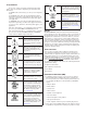
Safety Information Unit is compliant with European Union directives. See Declaration of Conformity for further details on Directives and Standards used for Compliance. We use note, caution and warning symbols throughout this book to draw your attention to important operational and safety information. A “NOTE” marks a short message to alert you to an important detail. Unit has been reviewed and approved by Factory Mutual as a Temperature Limit Device per FM Class 3545 standard. See: www. fmglobal.
repair or evaluation. Make sure the RMA number is on the outside of the carton and on all paperwork returned. Ship on a Freight Prepaid basis. 3. After we receive your return, we will examine it and try to verify the reason for returning it. 4. In cases of manufacturing defect, we will enter a repair order, replacement order or issue credit for material returned. In cases of customer misuse, we will provide repair costs and request a purchase order to proceed with the repair work. 5.
TC Table of Contents Chapter 1: Overview . . . . . . . . . . . . . . . . . . . . . . . . . . . . . . . . . . . . . 4 A Conceptual View of the RMC Module. . . . . . . . . . . . . . . . . . . . . . . . . . 7 Getting Started Quickly. . . . . . . . . . . . . . . . . . . . . . . . . . . . . . . . . . . . . . . 7 Chapter 2: Install and Wire. . . . . . . . . . . . . . . . . . . . . . . . . .
TC Table of Contents (cont.) Output Menu. . . . . . . . . . . . . . . . . . . . . . . . . . . . . . . . . . . . . . . . . . . . . . 81 Alarm Menu . . . . . . . . . . . . . . . . . . . . . . . . . . . . . . . . . . . . . . . . . . . . . . 84 Current Menu. . . . . . . . . . . . . . . . . . . . . . . . . . . . . . . . . . . . . . . . . . . . . 87 Linearization Menu. . . .
TC Table of Contents (cont.) Software Configuration. . . . . . . . . . . . . . . . . . . . . . . . . . . . . . . . . . . . . 169 Function Block Descriptions. . . . . . . . . . . . . . . . . . . . . . . . . . . . . . . . . 172 Chapter 8: Appendix . . . . . . . . . . . . . . . . . . . . . . . . . . . . . . . . . . . 217 Troubleshooting Alarms, Errors and Control Issues. . . . . . . . . . . . . .
1 Chapter 1: Overview Available EZ-ZONE RM System Literature and Resources Document Title and Part Number Description EZ-ZONE Rail Mount Access (RMA) User's Guide, part number: 0600-0072-0000 Describes how to connect the RM system into an industrial network, how to use data logging, module backup and the real-time clock. EZ-ZONE Rail Mount Expansion (RME) User's Guide, part number: 0600-0073-0000 When additional I/O is needed the Expansion module fills the gap.
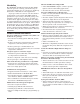
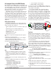
Introduction The EZ-ZONE ® Rail Mount Control module (RMC) takes the pain out of solving your thermal loop requirements whether it be for a single loop, multi-loop, stand-alone or distributed control applications. It just got a whole lot easier to solve the thermal requirements of your system. The RMC module is provided in a space-saving, rail-mount package and is highly scalable where you only pay for what you need.
Split-Rail Control (SRC) • Allows modules to be mounted together or mounted remotely from one another (maximum distance 200 feet or 61 meters) • Shares control operation via Synergistic Module Control (SMC) capability • Allows individual modules to be mounted closer to the physical input and output devices to which they are wired • Improves system reliability and lowers wiring costs Factory Mutual (FM) Approved Safety Limit • Increases user and equipment safety for over/under temperature conditions • Suppor
A Conceptual View of the RMC Module The flexibility of the RMC software and hardware allows a large range of configurations. Acquiring a better understanding of the controller’s overall functionality and capabilities while at the same time planning out how the controller can be used will deliver maximum effectiveness in your application.
This configuration is now complete. When the selected digital input is active the alarm or all alarms that are latched without a currently existing alarm condition will be reset. If a specific alarm instance (1 - 8) is selected (step 5) it will be that instance alone that will be reset. ue is greater than the alarm high set point, the realworld output will be driven on.
A Conceptual View of RM Hardware Configurations Due to the scalability and flexibility in the RM system a user has several options available in the way that the hardware can be connected. Listed below are a few examples.
RM Control Module Connected to an OIT Running Modbus RTU In this configuration the control module connected to the OIT is equipped with the Modbus RTU protocol (RMCxxxxxxxxx1xx). It is important to note that Modbus communications takes place between the OIT and the control it is connected to. The RM backplane is always using the Standard Bus protocol.
EZ-ZONE RM-Control Module - System Diagram with 6-Digital Input/Output card in slot E Input Function Input Sensor Output Function Analog Input 1, 2, 3, 4 None, CT, Thermocouple, RTD (100, 1k), Thermistor (5k, 10K, 20k, 40k), Process (mV, V, mA) or 1k Potentionmeter Current Transformer Sense (CT), Limit or PID Controller (When ordered, all loops have Ramp/ Soak, max 25 files & 400 steps.
Input Function Input Sensor EZ-ZONE RM-Control Module - System Diagram without 6-Digital Input/Output card in slot E Output Function Analog Input 1, 2, 3, 4 None, CT, Thermocouple, RTD (100, 1k), Thermistor (5k, 10K, 20k, 40k), Process (mV, V, mA) or 1k Potentionmeter Current Transformer Sense (CT), Limit or PID Controller Output 1, 3, 5, 7 None, Switched dc/Open Collector, 5A Mechanical Relay Form C, Process, or 0.
2 Chapter 2: Install and Wire Dimensions As can be seen below the dimensions of the RMC module will change slightly based on the type of connector used. Module Removal Clearance Standard Connectors 147.07 mm ( 5.8 in ) 75.08 mm ( 3.0 in ) 44.45 mm ( 1.75 in ) 101.60 mm ( 4.00 in ) 116.08 mm ( 4.57 in ) 15 51.56 mm ( 2.03 in ) Latch in open position 0 165 mm ( 6.50 in ) Module Removal Displacement Module Removal Clearance Straight Connectors 155 mm ( 6.10 ) 75.08 mm ( 3.0 in ) 44.45 mm ( 1.
Dimensions Chassis Mount Front View (Module Removed) - Screw Connection Pattern 58.67 mm ( 2.31 in ) 17.53 mm ( 0.69 in ) 32.77 mm ( 1.29 in ) 51.56 mm ( 2.03 in ) 60.45 mm ( 2.38 in ) 35.81 mm ( 1.41 in ) 35.05 mm ( 1.38 in ) 16.76 mm ( 0.67 in ) The view above is representative of the modular backplane without the module. Recommended chassis mount hardware: 1. #8 screw, 3/4" long 2. Torque to 10 -15 in-lb 3.
Power Supplies DSP60 DSP30 55.6 mm 2.189 in ++ - - L DC OK DSP60 N L N 5 6 6 14.20 mm 0.559 in 14.20 mm 0.559 in 5 Power Supply Specifications DSP100 DSP 30 56.8 mm 2.236 in 89.9 mm 3.539 in 49.00 mm 1.929 in 12 3 4 vout ADJ. 32.10 mm 1.264 in DC LO DC OK 5 6 14.20 mm 0.559 in 5 N 9.75 mm 0.384 in L 43.1 mm 1.697 in DSP100 91.00 mm 3.583 in 91.00 mm 3.583 in ++ - - 32.10 mm 1.264 in DC LO 91.00 mm 3.583 in 9.75 mm 0.384 in DSP30 1.697 in DC OK vout ADJ. 91.00 mm 3.
RMC Installation and Removal on a DIN Rail Modular Backplane Connector The picture on the right shows the Modular Backplane Connector, both front and rear view. The rear view is bringing in to focus a metal clip. If the DIN rail is grounded the Modular Backplane Connector and the module connected to it will be also (recommended).
Module Removal To remove a module from the Modular Backplane Connector find the red tab protruding from the bottom of the module and pull back on it as shown to the right. While pulling back on the red tab the two mounting posts will release the module where the module can then be lifted up and out of the Modular Backplane Connector.
Wiring Controller Module (RMCxxxxxxxxxxxx) Slot A Slot B Slot D Slot E Terminal Function Inputs 1 Configuration Universal, RTD, Potentiometer and Thermistor Inputs 1 - 4 2 3 4 T1 S1 T2 S2 T3 S3 T4 S4 R1 R2 R3 R4 T_ (RTD) or current +S_ (RTD), thermocouple -, current -, potentiometer or volts R_ (RTD), thermocouple + or volts +, potentiometer wiper Input Input Input Input Universal/Thermistor Input Part # Digits 4, 6, 8, 10 1: RMC[1,2,3,4,5,6]xxxxxxxxxxx 2: RMCxx[1,2,5,6]xxxxxxxxx 3: RMC
Controller Module (RMCxxxxxxxxxxxx) Slot A Slot B Slot D Slot E Terminal Function Outputs (cont.
RMC Front View Standard Connector Slot D Slot E Slot A Slot B 98 99 power Watlow EZ-ZONE ® RMC Module • 20 • Chapter 2 Install and Wire
RMC Module Isolation Diagram Mechanical Relay, Solid-State Relay, NO-ARC Relay Outputs Digital Inputs & Outputs No Isolation Switched DC, Open Collector, Process outputs Low-voltage Isolation Analog Input 1 - 4 Safety Isolation Safety Isolation Controller Power Supply 20.4 to 30.8VÎ (dc) 20.4 to 30.
Warning: ç Use National Electric (NEC) or other country-specific standard wiring and safety practices when wiring and connecting this controller to a power source and to electrical sensors or peripheral devices. Failure to do so may result in damage to equipment and property, and/or injury or loss of life. Controller Module Wiring (RMCxxxxxxxxxxxx) Low Power power Maximum wire size termination and torque rating: • 0.0507 to 3.30 mm2 (30 to 12 AWG) single-wire termination or two 1.31 mm2 (16 AWG) • 0.
Warning: ç Input 1, 2, 3, 4 Thermistor • >20 MΩ input impedance Input 1: RMC(2,4,6)xxxxxxxxxxx Input 2: RMCxx(2,6)xxxxxxxxx Input 3: RMCxxxx(2,6)xxxxxxx Input 4: RMCxxxxxx(2,6)xxxxx Slot A, B, D, E Use National Electric (NEC) or other country-specific standard wiring and safety practices when wiring and connecting this controller to a power source and to electrical sensors or peripheral devices. Failure to do so may result in damage to equipment and property, and/or injury or loss of life.
Warning: ç Input 1, 2, 3, 4 Potentiometer • Use a 1 kΩ potentiometer. Input 1: RMC(1,3,5)xxxxxxxxxxx (S1/R1) Input 2: RMCxx(1,5)xxxxxxxxx (S2/R2) Input 3: RMCxxxx(1,5)xxxxxxx (S3/R3) Input 4: RMCxxxxxx(1,5)xxxxx (S4/R4) Slot A, B, D, E Use National Electric (NEC) or other country-specific standard wiring and safety practices when wiring and connecting this controller to a power source and to electrical sensors or peripheral devices.
Warning: ç Digital Inputs 7 through 12 Slot E Use National Electric (NEC) or other country-specific standard wiring and safety practices when wiring and connecting this controller to a power source and to electrical sensors or peripheral devices. Failure to do so may result in damage to equipment and property, and/or injury or loss of life. Common B7 DC Input D7 DC Input Note: Maximum wire size termination and torque rating: • 0.0507 to 3.30 mm2 (30 to 12 AWG) single-wire termination or two 1.
Warning: ç Switched DC Wiring Example Using DO 7-12 Use National Electric (NEC) or other country-specific standard wiring and safety practices when wiring and connecting this controller to a power source and to electrical sensors or peripheral devices. Failure to do so may result in damage to equipment and property, and/or injury or loss of life. Collector Outputs Common B_ D_ D_ Htr 1 + + + - Note: Maximum wire size termination and torque rating: • 0.0507 to 3.
Warning: ç Use National Electric (NEC) or other country-specific standard wiring and safety practices when wiring and connecting this controller to a power source and to electrical sensors or peripheral devices. Failure to do so may result in damage to equipment and property, and/or injury or loss of life.
Warning: ç Use National Electric (NEC) or other country-specific standard wiring and safety practices when wiring and connecting this controller to a power source and to electrical sensors or peripheral devices. Failure to do so may result in damage to equipment and property, and/or injury or loss of life.
Warning: ç Use National Electric (NEC) or other country-specific standard wiring and safety practices when wiring and connecting this controller to a power source and to electrical sensors or peripheral devices. Failure to do so may result in damage to equipment and property, and/or injury or loss of life.
Warning: ç Outputs 1, 3, 5, 7 Solid-State Relay, Form A Use National Electric (NEC) or other country-specific standard wiring and safety practices when wiring and connecting this controller to a power source and to electrical sensors or peripheral devices. Failure to do so may result in damage to equipment and property, and/or injury or loss of life.
Quencharc Wiring Example In this example the Quencharc circuit (Watlow part# 0804-01470000) is used to protect the RMC internal circuitry from the counter electromagnetic force from the inductive user load when de-engergized. It is recommended that this or an equivalent Quencharc be used when connecting inductive loads to RMC outputs. User Load L_ N Quencharc K_ Standard Bus EIA-485 Communications Slot C 98 99 CF CD CE CZ CX CY T-/R- T+/R+ common • Wire T-/R- to the A terminal of the EIA485 port.
Modbus RTU or Standard Bus EIA-485 Communications Slot C 98 99 CC CA CB CZ CX CY T-/R- T+/R+ common • Wire T-/R- to the A terminal of the EIA-485 port. • Wire T+/R+ to the B terminal of the EIA-485 port. • Wire common to the common terminal of the EIA-485 port. • Do not route network wires with power wires. Connect network wires in daisy-chain fashion when connecting multiple devices in a network. • A termination resistor may be required.
EZ-ZONE® RM to B&B Converter TM Model ULINX 485USBTB-2W USB to RS-485 Adapter using Modbus RTU EZ ZONE R RM 1 D D 98 99 CC CA CB CZ CX CY USB ULINX TM USB Serial Conversion Model 485TB-2W B&B electronics A M 1 9 2 10 3 11 4 12 5 13 6 14 7 15 8 16 B A(-) B(+) A(-) B(+) GND Slot C PC Software Protocol - Modbus RTU Third Party Data format 9,600, 19,200, 38,400 baud 8 data bits even, odd, no parity 1 start bit 1 stop bit B S E Use twisted pair wires such as Cat 5 cabling.
To modify Latency Timer settings follow the steps below: 1. Navigate to Device Manager. 2. Double click on Ports. 3. Right click on the USB serial port in use and select Properties. 4. Click the tab labeled Port settings and then click the Advance button.
Wiring a Serial EIA-485 Network Do not route network wires with power wires. Connect network wires in daisy-chain fashion when connecting multiple devices in a network. A termination resistor may be required. Place a 120 Ω resistor across T+/R+ and T-/R- of the last controller on a network. Only one protocol per port is available at a time: either Modbus RTU or Standard Bus. Note: Termination resistors when used, require a termination resistor at both ends of the network.
Connecting the Modules RM System Connections The RMC module can be installed as stand-alone modules or can be interconnected on the DIN rail as shown below. When modules are connected together as shown, power and communications are shared between modules over the modular backplane interconnection. Therefore, bringing the necessary power and communications wiring to any one connector in slot C is sufficient.
Conventions Used in the Menu Pages To better understand the menu pages that follow review the naming conventions used. When encountered throughout this document, the word "default" implies as shipped from the factory. Each page (Operations, Setup, Profile and Factory) and their associated menus have identical headers defined below: Header Name the RUI (optional equipment) visual information from the control is displayed to the observer using a fairly standard 7 segment display.
Note: In this User's Guide all values shown representing Modbus addresses are added to 400,001 or 40,001 to acquire the absolute address. As an example, notice above (under the Range header) the Modbus address identified for Sensor type. Compare this to the value listed for this same parameter found in the Setup Page under the Analog Input Menu. For parameters listed as float notice that only one (low order) of the two registers is listed, this is true throughout this document.
3 Chapter 3: Operations Pages Control Module Operation Page Parameters To navigate to the Operations Page using the RUI, follow the steps below: 1. From the Home Page, press both the Up ¿ and Down ¯ keys for three seconds. [``Ai] will appear in the upper display and [oPEr] will appear in the lower display. 2. Press the Up ¿ or Down ¯ key to view available menus. the Up ¿ or Down ¯ key to select and then press the Advance Key ‰ to enter. 5.
[`CPE] [oPEr] Compare Menu [```1] [`CPE] Compare (1 to 4) [`Su;A] Source Value A [`Su;b] Source Value B [``o;u] Output Value [tMr] [oPEr] Timer Menu [```1] [tMr] Timer (1 to 4) [`Su;A] Source Value A [`Su;b] Source Value B [``E;t] Elapsed Time [``o;u] Output Value [`Ctr] [oPEr] Counter Menu [```1] [`Ctr] Counter (1 to 4) [`Cnt] Count [`Su;A] Source Value A [`Su;b] Source Value B [``o;u] Output Value [`LgC] [oPEr] Logic Menu [```1] [`LgC] Logic (1 to 4) [`Su;A] Source Valu
RMC Module • Operations Page Display Parameter Name Description Range Default Modbus Relative Address CIP Class Instance Attribute hex (dec) Data Profibus Parameter Type Index ID & Read/ Write [``Ai] [oPEr] Analog Input Menu -1,999.000 to 9,999.000°F or ``Ain] Analog Input (1 to 4) Value units [ Ain] View the process value. -1,128.000 to 5,537.000°C Note: Ensure that the Error Status (below) indicates no error (61) when reading this value using a field bus protocol.
RMC Module • Operations Page Display Parameter Name Description Range Default Modbus Relative Address CIP Class Instance Attribute hex (dec) Data Profibus Parameter Type Index ID & Read/ Write [`Su;C] [ Su.C] Process Value (1 to 4) -1,999.000 to 9,999.000°F or Source Value C units View the value of Source -1,128.000 to 5,537.000°C C. ---- 3434 [offset 70] 0x7E (126) 1 to 4 0x12 (18) ---- 26018 float R [`Su;d] [ Su.d] Process Value (1 to 4) -1,999.000 to 9,999.
RMC Module • Operations Page Parameter Name Description Display No Display Digital Input (7 to 12) Source Error View reported cause for input malfunction.
RMC Module • Operations Page Display Parameter Name Description Range Default Modbus Relative Address CIP Class Instance Attribute hex (dec) Data Profibus Parameter Type Index ID & Read/ Write [`h;Pr] [ h.Pr] Monitor (1 to 4) Heat Power View the current heat output level. 0.0 to 100.0% ---- 2244 [offset 70] 0x97 (151) 1 to 4 0xD (13) ---- 8011 float R [`C;Pr] [ C.Pr] Monitor (1 to 4) Cool Power View the current cool output level. -100.0 to 0.
RMC Module • Operations Page Display Parameter Name Description Range Default Modbus Relative Address CIP Class Instance Attribute hex (dec) Data Profibus Parameter Type Index ID & Read/ Write [A;tSP] [A.tSP} Control Loop (1 to 4) Autotune Set Point Set the set point that the autotune will use, as a percentage of the current set point. 50.0 to 200.0% 90.
RMC Module • Operations Page Display Parameter Name Description Range Default [``ti] [ ti] Control Loop (1 to 4) Time Integral Set the PID integral for the outputs. 0 to 9,999 seconds per repeat 180 seconds per repeat [``td] [ td] Control Loop (1 to 4) Time Derivative Set the PID derivative time for the outputs. 0 to 9,999 seconds 0 [``dB] [ db] Control Loop (1 to 4) Dead Band Set the offset to the proportional band.
RMC Module • Operations Page Parameter Name Description Display Range Default Modbus Relative Address CIP Class Instance Attribute hex (dec) Data Profibus Parameter Type Index ID & Read/ Write [ALM] [oPEr] Alarm Menu [`A;Lo] [ A.Lo] Alarm (1 to 8) Low Set Point If Alarm Type (Setup Page, Alarm Menu) is set to: process - set the process value that will trigger a low alarm. deviation - set the span of units from the closed loop set point that will trigger a low alarm.
RMC Module • Operations Page Display Parameter Name Description Range Default Modbus Relative Address CIP Class Instance Attribute hex (dec) Data Profibus Parameter Type Index ID & Read/ Write [`a;st] [ A.St] Alarm (1 to 8) Alarm State Current state of alarm Startup (88) None (61) Blocked (12) Alarm low (8) Alarm high (7) Error (28) ---- 1756 [offset 60] 0x6D (109) 1 to 8 9 ---- 9009 uint R No Display Alarm (1 to 8) Alarm Clearable Read to see if alarm can be cleared.
RMC Module • Operations Page Display Parameter Name Description Range Default Modbus Relative Address CIP Class Instance Attribute hex (dec) Data Profibus Parameter Type Index ID & Read/ Write [`h;Er] [ h.Er] Current (1 to 4) Heater Error View the cause of the most recent load fault monitored by the current transformer.
RMC Module • Operations Page Parameter Name Description Display Range Default Modbus Relative Address CIP Class Instance Attribute hex (dec) Data Profibus Parameter Type Index ID & Read/ Write [``o;u] [ o.v] Compare (1 to 4) Output Value View the value of this function's output.
RMC Module • Operations Page Parameter Name Description Display Range Default Modbus Relative Address CIP Class Instance Attribute hex (dec) Data Profibus Parameter Type Index ID & Read/ Write [`Ctr] [oPEr] Counter Menu [`Cnt] [ Cnt] Counter (1 to 4) Count View the function's total count. 0 to 9,999 ---- 4188 [offset 40] 0x82 (130) 1 to 4 0xF (15) 217 30015 uint R [`Su;A] [ Su.A] Counter (1 to 4) Source Value A View the value of Source A.
RMC Module • Operations Page Parameter Name Description Display Range Default Modbus Relative Address CIP Class Instance Attribute hex (dec) Data Profibus Parameter Type Index ID & Read/ Write [`Su;E] [ Su.E] Logic (1 to 4) Source Value E View the value of Source E. [`off] Off (62) [``on] On (63) ---- 3736 [offset 80] 0x7F (127) 1 to 4 0x1D (29) ---- 27029 uint R [`Su;F] [ Su.F] Logic (1 to 4) Source Value F View the value of Source F.
RMC Module • Operations Page Display Parameter Name Description Range Default ---- Modbus Relative Address CIP Class Instance Attribute hex (dec) Data Profibus Parameter Type Index ID & Read/ Write 2878 [offset 70] 0x7D (125) 1 to 8 0x14 (20) ---- 25020 uint R 2884 [offset 70] 0x7D (125) 1 to 8 0x17 (23) ---- 25023 float RWES ---- 2882 [offset 70] 0x7D (125) 1 to 8 0x16 (22) ---- 25022 float R None (61) Open (65) Shorted (127) Measurement Error (140) Bad Cal Data (139) Ambient Error
RMC Module • Operations Page Display Parameter Name Description Range Default Modbus Relative Address CIP Class Instance Attribute hex (dec) Data Profibus Parameter Type Index ID & Read/ Write [`o;u2] [ o.v2] Special Output Function (1 to 4) Output Value 2 View the value of this function's Output 2. -1,999.000 to 9,999.000°F or units -1,128.000 to 5,537.
RMC Module • Operations Page Display Parameter Name Description [P;Sta] [oPEr] Profile Status Menu Range Default Modbus Relative Address CIP Class Instance Attribute hex (dec) Data Profibus Parameter Type Index ID & Read/ Write * Some parameters in the Profile Status Menu can be changed for the currently running profile, but should only be changed by knowledgeable personnel and with caution.
RMC Module • Operations Page Display Parameter Name Description Range Default Modbus Relative Address CIP Class Instance Attribute hex (dec) Data Profibus Parameter Type Index ID & Read/ Write [t;SP3] [t.SP3] Profile Status *Target Set Point Loop 3 View or change the target set point of the current step. -1,999.000 to 9,999.000°F or units -1,128.000 to 5,537.000°C 0.0°F or units -18.0°C 5376 0x7A (122) 1 0x31 (49) ---- 22049 float RW [t;SP4] [t.
RMC Module • Operations Page Display Parameter Name Description Range Default Modbus Relative Address CIP Class Instance Attribute hex (dec) Data Profibus Parameter Type Index ID & Read/ Write [hoUr] [hoUr] Profile Status Hours Step time remaing in hours. 0 to 99 0 5434 0x7A (122) 1 0x4E (78) ---- 22078 uint RW [min] [ Min] Profile Status Minutes Step time remaing in minutes.
RMC Module • Operations Page Display Parameter Name Description Range Default Modbus Relative Address CIP Class Instance Attribute hex (dec) Data Profibus Parameter Type Index ID & Read/ Write [Ent1] [Ent1] Profile Status *Active Event Output 1 View or change the event output states. [`off] Off (62) [``on] On (63) Off 5306 0x7A (122) 1 0xE (14) ---- 22014 uint RW [Ent2] [Ent2] Profile Status *Active Event Output 2 View or change the event output states.
RMC Module • Operations Page Display No Display Parameter Name Description Profile Status Profile State Read currentProfile state. Range Default Off (62) Running (149) Pause (146) ---- Note: Some values will be rounded off to fit in the four-character display. Full values can be read with other interfaces. Note: If there is only one instance of a menu, no submenus will appear.
4 Chapter 4: Setup Pages Control Module Setup Page Parameters To navigate to the Setup Page using the RUI, follow the steps below: 1. From the Home Page, press and hold both the Up ¿ and Down ¯ keys for six seconds. [``Ai] will appear in the upper display and [`Set] will appear in the lower display. Note: If keys are released when [OPEr] is displayed, press the Infinity Key ˆ or reset key to exit and repeat until [`Set] is displayed. 2. Press the Up ¿ or Down ¯ key to view available menus. 4.
[`h;hy] Heat Hysteresis ** [`C;Pb] Cool Proportional Band ** [`C;hy] Cool Hysteresis ** [``ti] Time Integral ** [``td] Time Derivative ** [``db] Dead Band ** [t;tUn] TRU-TUNE+® Enable [t;bnd] TRU-TUNE+ Band [`t;gn] TRU-TUNE+ Gain [A;tSP] Autotune Set Point ** [t;Agr] Autotune Aggressiveness [`P;dl] Peltier Delay [`r;En] Remote Set Point Enable [SFn;b] Source Function B [`Si;b] Source Instance B [`S2;b] Source Zone B [`r;ty] Remote Set Point Type [`UFA] U
[SFn;E] Source Function E [`Si;E] Source Instance E [`S2;E] Source Zone E [`S;Lo] Scale Low [`S;hi] Scale High [Unit] Units [`r;Lo] Range Low [`r;hi] Range High [p;unt] Pressure Units [a;unt] Altitude Units [`FiL] Filter [`SoF] [`Set] Special Output Function Menu [```1] [`SoF] Special Output Function 1 to 4 [``Fn] Function [SFn;A] Source Function A [`Si;A] Source Instance A [`S2;A] Source Zone A [SFn;B] Source Function B [`Si;B] Source Instance B [`S2;B] Sourc
RMC Module • Setup Page Display Parameter Name Description Range Default Modbus Relative Address CIP Class Instance Attribute hex (dec) Data Profibus Parameter Type Index ID & Read/ Write [``Ai] [`Set] Analog Input Menu [`Sen] [ SEn] Analog Input (1 to 4) Sensor Type Set the analog sensor type to match the device wired to this input.
RMC Module • Setup Page Display Parameter Name Description Range Default -1,999.000 to 9,999.000 Modbus Relative Address CIP Class Instance Attribute hex (dec) Data Profibus Parameter Type Index ID & Read/ Write 0.0 392 0x68 (104) 1 to 4 [offset 90] 0x11 (17) 8 4017 float RWES 9,999 394 0x68 (104) 1 to 4 [offset 90] 0x12 (18) 9 4018 float RWES [`off] Off (62) [Low] Low (53) Off 418 0x68 (104) 1 to 4 [offset 90] 0x1E (30) 10 4030 uint RWES -100.0 to 1,000.0 0.
RMC Module • Setup Page Display Parameter Name Description Range [`i;Ca] [ i.CA] Analog Input (1 to 4) -1,999.000 to 9,999.000°F or Calibration Offset ** units Offset the input reading -1,110.555 to 5,555.000°C to compensate for lead wire resistance or other factors that cause the input reading to vary from the actual process value. [`Ain] [ Ain] Analog Input (1 to 4) -1,999.000 to 9,999.000°F or Value ** units View the process value. -1,128.000 to 5,537.
RMC Module • Setup Page Display Parameter Name Description Range Default Modbus Relative Address CIP Class Instance Attribute hex (dec) Data Profibus Parameter Type Index ID & Read/ Write [``Pu] [`Set] Process Value Menu [``Fn] [ Fn] Process Value (1 to 4) Function Set the function that will be applied to the source or sources.
RMC Module • Setup Page Display Parameter Name Description [SFn;C] Process Value (1 to 4) [SFn.C] Source Function C Set the type of function that will be used for this source.
RMC Module • Setup Page Display Parameter Name Description [SFn;E] Process Value (1 to 4) [SFn.E] Source Function E Set the type of function that will be used by this source to trigger a switch between Source A and Source B.
RMC Module • Setup Page Display Parameter Name Description [p;unt] [P.unt] Process Value (1 - 4) Pressure Units If Process Value function is set for Pressure to Altitude units, define units of measure for conversion. [a;unt] [A.
RMC Module • Setup Page Display Parameter Name Description Range Default [``Fn] [ Fn] Digital Output (7 to 12) Off [`oFF] Off (62) Function [``ai] Analog Input (142) Select what function will [ALM] Alarm (6) drive this output.
RMC Module • Setup Page Display Parameter Name Description Range Default Modbus Relative Address CIP Class Instance Attribute hex (dec) Data Profibus Parameter Type Index ID & Read/ Write [`o;Ct] [ o.Ct] Digital Output (7 to 12) Control Set the output control type. This parameter is only used with PID control, but can be set anytime. [`Ftb] Fixed Time Base (34) [`utb] Variable Time Base (103) Fixed Time Base 1204 [offset 30] 0x6A (106) 7 to 12 2 85 6002 uint RWES [`o;tb] [ o.
RMC Module • Setup Page Display Parameter Name Description Range Default Modbus Relative Address CIP Class Instance Attribute hex (dec) Data Profibus Parameter Type Index ID & Read/ Write [`ACt] [`SEt] Action Menu [``Fn] [ Fn] Action (1 to 8) Function Set the action that will be triggered by this function. Note: The Limit Reset function is not available in this menu for firmware revision 6.0 and above. To reset a tripped limit see the section entitled "Resetting a Tripped Limit".
RMC Module • Setup Page Display Parameter Name Description [SFn;A] Action (1 to 8) [SFn.A] Source Function A Set the event or function that will trigger the action.
RMC Module • Setup Page Modbus Relative Address CIP Class Instance Attribute hex (dec) Data Profibus Parameter Type Index ID & Read/ Write Display Parameter Name Description [`L;hy] [ L.hy] Limit (1 to 4) Hysteresis Set the hysteresis for the limit function. This determines how far into the safe range the process value must move before the limit can be cleared. 0.001 to 9,999.000°F or units 0.001 to 5,555.000°C 3.0°F or units 2.
RMC Module • Setup Page Display Parameter Name Description Range Default Modbus Relative Address CIP Class Instance Attribute hex (dec) Data Profibus Parameter Type Index ID & Read/ Write [LooP] [`Set]] Control Loop Menu Analog Input [``Ai] Analog Input (142) [SFn;A] Control Loop (1 to 4) [SFn.A] Source Function A [``Pu] Process Value (241) Set the type of function that will be used for this source. ---- 2276 0x97 (151) [offset 70] 1 to 4 0x1D (29) ---- 8050 RWE ---- 8021 R [`is;a] [ iS.
RMC Module • Setup Page Display Parameter Name Description [`C;hy] [ C.hy] Control Loop (1 to 4) Cool Hysteresis ** Set the control switching hysteresis for on-off control. This determines how far into the “on” region the process value needs to move before the output turns on. 0.001 to 9,999.000°F or units 0.001 to 5,555.000°C 3.0°F or units 2.0°C [``ti] [ ti] Control Loop (1 to 4) Time Integral ** Set the PID integral for the outputs.
RMC Module • Setup Page Modbus Relative Address CIP Class Instance Attribute hex (dec) Data Profibus Parameter Type Index ID & Read/ Write Display Parameter Name Description [A;tSP] [A.tSP} Control Loop (1 to 4) Autotune Set Point ** Set the set point that the autotune will use, as a percentage of the current set point. 50.0 to 200.0% 90.0 2258 [offset 70] 0x97 (151) 1 to 4 0x14 (20) ---- 8025 float RWES [t;Agr] [t.
RMC Module • Setup Page Display Parameter Name Description Range Default Modbus Relative Address CIP Class Instance Attribute hex (dec) Data Profibus Parameter Type Index ID & Read/ Write [`r;ty] [ r.ty] Control Loop (1 to 4) [AUto] Auto (10) Remote Set Point Type [MAn] Manual (54) Set what type of set point will be used.
RMC Module • Setup Page Display Parameter Name Description [`L;dd] [ L.dd] Control Loop (1 to 4) Open Loop Detect Deviation Set the value that the process must deviate from the set point to trigger an open-loop error. -1,999.000 to 9,999.000°F or units -1,110.555 to 5,555.000°C [``rP] [ rP] Control Loop (1 to 4) Ramp Action Select when the controller's set point will ramp to the defined end set point. [`oFF] [`Str] [StPt] [both] [`r;SC] [ r.
RMC Module • Setup Page Display Parameter Name Description Range Default -100.0 to 100.0% Modbus Relative Address CIP Class Instance Attribute hex (dec) Data Profibus Parameter Type Index ID & Read/ Write -100 2508 [offset 80] 0x6B (107) 1 to 4 5 54 7005 float RWES 100 2510 [offset 80] 0x6B (107) 1 to 4 6 55 7006 float RWES -100.0 to 100.0% (heat and cool) 0 to 100.0% (heat only) -100.0 to 0% (cool only) 0.
RMC Module • Setup Page Display Parameter Name Description Range Default Modbus Relative Address CIP Class Instance Attribute hex (dec) Data Profibus Parameter Type Index ID & Read/ Write [otpt] [`Set] Output Menu [``Fn] [ Fn] Output Digital (1 to 8) off [`oFF] Off (62) Function [``ai] Analog Input (142) Select what function will [ALM] Alarm (6) drive this output.
RMC Module • Setup Page Display Parameter Name Description Range Default Modbus Relative Address CIP Class Instance Attribute hex (dec) Data Profibus Parameter Type Index ID & Read/ Write [`S2;A] [ SZ.A] Output Digital (1 to 8) Source Zone A Set the instance of the function selected above. 0 to 16 0 1042 [offset 30] 0x6A (106) 1 to 8 0xC (12) ---- 6012 uint RWES [`o;Ct] [ o.Ct] Output Digital (1 to 8) Control Set the output control type.
RMC Module • Setup Page Display Parameter Name Description Range Default Modbus Relative Address CIP Class Instance Attribute hex (dec) Data Profibus Parameter Type Index ID & Read/ Write [``Fn] [ Fn] Output Process (1, 3, 5 or 7) Function Set the type of function that will drive this output.
RMC Module • Setup Page Display Parameter Name Description Range Default Modbus Relative Address CIP Class Instance Attribute hex (dec) Data Profibus Parameter Type Index ID & Read/ Write [`S;hi] [ S.hi] Output Process (1, 3, 5 -100.0 to 100.0 or 7) Scale High Set the scale high for process output in electrical units. This value, in volts or milliamps, will correspond to 0% PID power output or the range high value. 10.
RMC Module • Setup Page Display Parameter Name Description Range Default CIP Class Instance Attribute hex (dec) Data Profibus Parameter Type Index ID & Read/ Write 1 1774 [offset 60] 0x6D (109) 1 to 8 0x12 (18) 22 9018 uint RWES Alarm (1 to 8) 0 or 16 Source Zone Set the zone of the function selected above.
RMC Module • Setup Page Display Parameter Name Description [`A;hi] [ A.hi] Alarm (1 to 8) High Set Point ** If Alarm Type (Setup Page, Alarm Menu) is set to: process - set the process value that will trigger a high alarm. deviation - set the span of units from the closed loop set point that will trigger a low alarm. A negative set point represents a value below closed loop set point. A positive set point represents a value above closed loop set point. -1,999.000 to 9,999.000°F or units -1,128.
RMC Module • Setup Page Modbus Relative Address CIP Class Instance Attribute hex (dec) Data Profibus Parameter Type Index ID & Read/ Write Display Parameter Name Description [a;Clr] [A.CLr] Alarm (1 to 8) Alarm Clear Request ** Write to this register to clear an alarm 0 ---- 1764 [offset 60] 0x6D (109) 1 to 8 0xD (13) 32 9013 uint W [A;sir] [A.
RMC Module • Setup Page Display [`C;;Si] [ C.Si] Parameter Name Description Range Default Current (1 to 4) 1 to 250 Output Source Instance With Current Output Source Instance, set the output on which the current will be monitored.
RMC Module • Setup Page Display Parameter Name Description Range Default Modbus Relative Address CIP Class Instance Attribute hex (dec) Data Profibus Parameter Type Index ID & Read/ Write [`iP;1] [ ip.1] Linearization (1 to 4) Input Point 1 Set the value that will be mapped to output 1. -1,999.000 to 9,999.000 0.0 4534 0x86 (134) [offset 70] 1 to 4 8 157 34008 float RWES [`oP;1] [ op.1] Linearization (1 to 4) Output Point 1 Set the value that will be mapped to input 1. -1,999.000 to 9,999.
RMC Module • Setup Page Display Parameter Name Description Range Default Modbus Relative Address CIP Class Instance Attribute hex (dec) Data Profibus Parameter Type Index ID & Read/ Write [`iP;7] [ ip.7] Linearization (1 to 4) Input Point 7 Set the value that will be mapped to output 7. -1,999.000 to 9,999.000 6.0 4546 0x86 (134) [offset 70] 1 to 4 E (14) 169 34014 float RWES [`oP;7] [ op.7] Linearization (1 to 4) Output Point 7 Set the value that will be mapped to input 7. -1,999.
RMC Module • Setup Page Display Parameter Name Description [SFn;A] Compare (1 to 4) [SFn.A] Source Function A Set the type of function that will be used for this source.
RMC Module • Setup Page Display Parameter Name Description [`Er;h] [ Er.h] Compare (1 to 4) Error Handling Use Error Handling to select the output value and error output state of this function if it receives an error signal from one or more sources and it cannot determine the output value.
RMC Module • Setup Page Display Parameter Name Description Range Default 1 to 250 Modbus Relative Address CIP Class Instance Attribute hex (dec) Data Profibus Parameter Type Index ID & Read/ Write 1 4324 0x83 (131) [offset 50] 1 to 4 3 ---- 31003 uint RWES 0 4328 0x83 (131) [offset 50] 1 to 4 5 ---- 31005 uint RWES High 4340 0x83 (131) [offset 50] 1 to 4 0xB (11) ---- 31011 uint RWES [SFn;B] [SFn.
RMC Module • Setup Page Display [`S2;B] [ SZ.b] Parameter Name Description Timer (1 to 4) Source Zone B Set the zone of the function selected above. [sas;b] Timer (1 to 4) [SAS.b] Source Active State B Set what state will be read as on.
RMC Module • Setup Page Display Parameter Name Description [SFn;A] Counter (1 to 4) [SFn.A] Source Function A Set the type of function that will be used for the counter clock signal.
RMC Module • Setup Page Modbus Relative Address CIP Class Instance Attribute hex (dec) Data Profibus Parameter Type Index ID & Read/ Write Display Parameter Name Description [SFn;B] [SFn.b] Counter (1 to 4) Source Function B Set the type of function that will be used for the counter load signal.
RMC Module • Setup Page Display Parameter Name Description Range [trgt] [trgt] Counter (1 to 4) 0 to 9,999 Target Value Set the value that will turn the output value on. [`lAt] [ LAt] Counter (1 to 4) Latching Output latched.
RMC Module • Setup Page Display Parameter Name Description [SFn;A] Logic (1 to 4) [SFn.A] Source Function A Set the type of function that will be used for this source.
RMC Module • Setup Page Display Parameter Name Description Range Default [SFn;b] [SFn.b] Logic (1 to 4) None [none] None (61) Source Function B [ALM] Alarm (6) Set the type of function [`C;Pr] Cool Power, Control that will be used for this Loop (161) source.
RMC Module • Setup Page Display Parameter Name Description Range Default None [SFn;C] Logic (1 to 4) [none] None (61) [SFn.C] Source Function C [ALM] Alarm (6) Set the type of function [`C;Pr] Cool Power, Control that will be used for this Loop (161) source.
RMC Module • Setup Page Display Parameter Name Description Range Default [SFn;D] [SFn.d] Logic (1 to 4) None [none] None (61) Source Function D [ALM] Alarm (6) Set the type of function [`C;Pr] Cool Power, Control that will be used for this Loop (161) source.
RMC Module • Setup Page Display Parameter Name Description Range Default None [SFn;E] Logic (1 to 4) [none] None (61) [SFn.E] Source Function E [ALM] Alarm (6) Set the type of function [`C;Pr] Cool Power, Control that will be used for this Loop (161) source.
RMC Module • Setup Page Display Parameter Name Description Range Default None [SFn;F] Logic (1 to 4) [none] None (61) [ SFn.F] Source Function F [ALM] Alarm (6) Set the type of function [`C;Pr] Cool Power, Control that will be used for this Loop (161) source.
RMC Module • Setup Page Display Parameter Name Description Range Default [SFn;g] [SFn.g] Logic (1 to 4) None [none] None (61) Source Function G [ALM] Alarm (6) Set the type of function [`C;Pr] Cool Power, Control that will be used for this Loop (161) source.
RMC Module • Setup Page Display Parameter Name Description Range Default None [SFn;h] Logic (1 to 4) [none] None (61) [ SFn.h] Source Function H [ALM] Alarm (6) Set the type of function [`C;Pr] Cool Power, Control that will be used for this Loop (161) source.
RMC Module • Setup Page Display Parameter Name Description [`Er;h] [ Er.h] Logic (1 to 4) Error Handling Use to select the output value and error output state of this function if it receives an error signal from one or more sources and it cannot determine the output value.
RMC Module • Setup Page Display Parameter Name Description Range [`S2;A] [ SZ.A] Math (1 to 8) 0 to 16 Source Zone A Set the zone of the function selected above. [SFn;b;] [SFn.b] Math (1 to 8) Source Function B Set the type of function that will be used for this source. [`Si;B] [ Si.b] Math (1 to 8) Source Instance B Set the instance of the function selected above. [`S2;B] [ SZ.b] Math (1 to 8) 0 to 16 Source Zone B Set the zone of the function selected above. [SFn;C] Math (1 to 8) [SFn.
RMC Module • Setup Page Display Parameter Name Description Range [`S2;C] [ SZ.C] Math (1 to 8) 0 to 16 Source Zone C Set the zone of the function selected above. [SFn;D] [SFn.d] Math (1 to 8) Source Function D Set the type of function that will be used for this source. [`si;d] [ Si.d] Math (1 to 8) Source Instance D Set the instance of the function selected above. [`S2;D] [ SZ.d] Math (1 to 8) 0 to 16 Source Zone D Set the zone of the function selected above.
RMC Module • Setup Page Display Parameter Name Description [SFn;E] Math (1 to 8) [SFn.E] Source Function E Set the type of function that will be used for this source.
RMC Module • Setup Page Display Parameter Name Description Range Default Source [`Src] Source (1539) [nonE] None (61) [`A;tP] Absolute Temperature (1540) [`r;tp] Relative Temperature (1541) [PWr] Power (73) [`pro] Process (75) [``rh] Relative Humidty (1538) Modbus Relative Address CIP Class Instance Attribute hex (dec) Data Profibus Parameter Type Index ID & Read/ Write 2902 [offset 70] 0x7D (125) 1 to 8 0x20 (32) ---- 25032 uint RWES 0.
RMC Module • Setup Page Display Parameter Name Description Range Default None [SFn;A] Special Output (1 to 4) [nonE] None (61) [SFn.A] Source Function A [``ai] Analog Input (142) Set the type of function [`C;Pr] Cool Power, Control that will be used for this Loop (161) source.
RMC Module • Setup Page Display Parameter Name Description Range Default Modbus Relative Address CIP Class Instance Attribute hex (dec) Data Profibus Parameter Type Index ID & Read/ Write [Pon;A] [Pon.A] Special Output (1 to 4) -100.0 to 100.0% Power On Level 1 If Function is set to Compressor Control: Use Source A for a first loop to inform the function whether the compressor will soon be required.
RMC Module • Setup Page Display Parameter Name Description Range Default Modbus Relative Address CIP Class Instance Attribute hex (dec) Data Profibus Parameter Type Index ID & Read/ Write [`t;t] [ t.t] Special Output (1 to 4) 10 to 9,999 seconds Valve Travel Time If Function is set to Motorized Valve: Source A will determine the valve position. • Set this time in seconds representing the time that it will take the valve to travel between fully closed and fully open.
RMC Module • Setup Page Display Parameter Name Description Range Default Modbus Relative Address CIP Class Instance Attribute hex (dec) Data Profibus Parameter Type Index ID & Read/ Write [`o;S3] [ o.S3] Special Output (1 to 4) Output 3 Size 0 to 9,999 0 5018 0x87 (135) [offset 80] 1 to 4 0x1E (30) ---- 35030 float RWES [`o;S4] [ o.S4] Special Output (1 to 4) Output 4 Size 0 to 9,999 0 5020 0x87 (135) [offset 80] 1 to 4 0x1F (31) ---- 35031 float RWES [`t;dL] [ t.
RMC Module • Setup Page Display Parameter Name Description Range Default Modbus Relative Address CIP Class Instance Attribute hex (dec) Data Profibus Parameter Type Index ID & Read/ Write [gLbL] [`Set] Global Menu [`C_F] [ C_F] [AC;LF] Global [AC.LF] AC Line Frequency Set the frequency to the applied ac line power source. Global -2.00 to 2.00 Percent Synchronized Variable Time Base Used to acquire tighter accuracy when running a profile. A setting of +0.
RMC Module • Setup Page Display Parameter Name Description Range Default Modbus Relative Address CIP Class Instance Attribute hex (dec) Data Profibus Parameter Type Index ID & Read/ Write [`PRo] [`Set] Profile Menu Time 5354 0x7A (122) 1 0x26 (38) ---- 22038 uint RWE Profile [StPt] Set Point (85) Profile Type [`Pro] Process (75) Set the profile startup to be based on a set point or a process value.
RMC Module • Setup Page Display Parameter Name Description Range Default Modbus Relative Address CIP Class Instance Attribute hex (dec) Data Profibus Parameter Type Index ID & Read/ Write [GSd4] [gSd4] Profile 0.0 to 9,999.000°F or units Guaranteed Soak De- 0.0 to 5,555.000°C viation 4 Set the value of the deviation band that will be used in all profile step types. The process value for control loop 4 must enter the deviation band before the step can proceed. . 10.0°F or units 6.
RMC Module • Setup Page Display Parameter Name Description [SFn;A] Profile [SFn.A] Source Function A Set the type of function that will be used for this source. Source will be used in profile step type "Wait for Process or Event" as "Event 1".
RMC Module • Setup Page Modbus Relative Address CIP Class Instance Attribute hex (dec) Data Profibus Parameter Type Index ID & Read/ Write Display Parameter Name Description [SFn;b] [SFn.b] Profile Source Function B Set the type of function that will be used for this source.
RMC Module • Setup Page Display Parameter Name Description [SFn;];C] Profile [SFn.C] Source Function C Set the type of function that will be used for this source.
RMC Module • Setup Page Display Parameter Name Description [SFn;D] Profile [SFn.D] Source Function D Set the type of function that will be used for this source.
RMC Module • Setup Page Display Parameter Name Description Range 1 to 250 CIP Class Instance Attribute hex (dec) Data Profibus Parameter Type Index ID & Read/ Write 1 5398 0x7A (122) 1 0x3C (60) ---- 22060 uint RWE 0 5406 0x7A (122) 1 0x40 (64) ---- 22064 uint RWE None [nonE] None (61) [``Ai] Analog Input (142) [CUrr] Current (22) [`C;Pr] Cool Power, Control Loop (161) [`h;Pr] Heat Power, Control Loop (160) [PWr] Power, Control Loop (73) [`Lnr] Linearization (238) [MAt] Math (240) [``Pu]
RMC Module • Setup Page Display Parameter Name Description Range 1 to 250 CIP Class Instance Attribute hex (dec) Data Profibus Parameter Type Index ID & Read/ Write 1 5402 0x7A (122) 1 0x3E (62) ---- 22062 uint RWE 0 5410 0x7A (122) 1 0x42 (66) ---- 22066 uint RWE None [nonE] None (61) [``Ai] Analog Input (142) [CUrr] Current (22) [`C;Pr] Cool Power, Control Loop (161) [`h;Pr] Heat Power, Control Loop (160) [PWr] Power, Control Loop (73) [`Lnr] Linearization (238) [MAt] Math (240) [``Pu]
RMC Module • Setup Page Display [`PAr] [ PAr] Parameter Name Description Communications Parity Set the parity of this controller to match the parity of the serial network.
RMC Module • Setup Page Display Parameter Name Description No Dis- Communications play Modbus Address Select the Modbus address. Range Default 1 to 247 1 Modbus Relative Address 2822 CIP Class Instance Attribute hex (dec) ---- Data Profibus Parameter Type Index ID & Read/ Write ---- 17007 uint RWE Note: This applies if 13th digit in part number is equal to one. Note: Some values will be rounded off to fit in the four-character display. Full values can be read with other interfaces.
5 Chapter 5: Profiling Page How to Setup and Start a Profile First, consider some foundational profile setup features that once configured, will then be available for all profiles. Note: It should also be noted that to execute a profile for any given loop of control, profiles must be enabled for each loop; this can be found in the Loop Menu of the Setup Page. The screen shot below (EZ-ZONE Configurator software) graphically shows the settings that will apply to all profiles; e.g.
lected step settings. 6. Press the Up ¿ or Down ¯ keys to change the steps settings. 7. Press the Infinity Key ˆ at any time to return to the step number prompt. 8. Press the Infinity Key ˆ again to return to the profile number prompt. 9. From any point press and hold the Infinity Key ˆ for two seconds to return to the Home Page. If using EZ-ZONE Configurator software, simply click on the plus sign next to Profiles in the left hand column, as shown in the screen shot below.
Profiling Parameters [``p1] to [`p25] Profile 1 to 25 [``s1] to [`s15] Subroutine 1 to 15 [prof] [```1] to [`250] [S;typ] Step Type [C;M1] Control Mode Loop 1 [C;M2] Control Mode Loop 2 [C;M3] Control Mode Loop 3 [C;M4] Control Mode Loop 4 [t;SP1] Target Set Point Loop 1 [t;SP2] Target Set Point Loop 2 [t;SP3] Target Set Point Loop 3 [t;SP4] Target Set Point Loop 4 [hoUr] Hours [Min] Minutes [`SEC] Seconds [RATE] Rate [`P;E1] Step Wait For Process Enable [W;P1] W
RMC Module • Profile Page Display Parameter Name Description Range Default Modbus Relative Address CIP Class Instance Attribute hex (dec) Profibus Parameter Index ID Data Type & Read/ Write Unused 5440 [offset 100] 0x79 (121) 1 to (250) 1 ---- 21001 uint RWE Step (1 to 250) [AUto] Auto (10) Control Mode Loop 1 [`oFF] Off (62) Set the control mode [MAn] Manual (54) for this loop. Auto 5486 [offset 100] 0x79 (121) 1 to (250) 0x18 (24) ---- 21024 uint RWE [C;M2] [C.
RMC Module • Profile Page Display Parameter Name Description Range Default Modbus Relative Address CIP Class Instance Attribute hex (dec) Profibus Parameter Index ID Data Type & Read/ Write [hoUr] [hoUr] Step (1 to 250) Hours If step type is Time, enter time over which set point changes. If Soak or State Step, enter time to maintain this step.
RMC Module • Profile Page Display Parameter Name Description Range Default Modbus Relative Address CIP Class Instance Attribute hex (dec) Profibus Parameter Index ID Data Type & Read/ Write [W;P1] [W.P1] Step (1 to 250) Wait For Process 2 Enter a value that must be satisfied which is specified by Source F in Profile Setup. -1,999.000 to 9,999.000°F or units -1,128.000 to 5,537.000°C 0.0°F or units -18.0°C 5500 [offset 100] 0x79 (121) 1 to (250) 0x1F (31) ---- 21031 float RWE [`P;E3] [P.
RMC Module • Profile Page Display Parameter Name Description Range Default Modbus Relative Address CIP Class Instance Attribute hex (dec) Profibus Parameter Index ID Data Type & Read/ Write [WE;3] [WE.3] Step (1 to 250) Wait Event 3 Select a state that must be satisfied which is specified by Source C in Profile Setup. [nonE] None (61) [``on] On (63) [`oFF] Off (62) None 5482 [offset 100] 0x79 (121) 1 to (250) 0x16 (22) ---- 21022 uint RWE [WE;4] [WE.
RMC Module • Profile Page Display Parameter Name Description Range Default Modbus Relative Address CIP Class Instance Attribute hex (dec) Profibus Parameter Index ID Data Type & Read/ Write [``SC] [ SC] Step (1 to 250) Subroutine Count If step type is Subroutine, specify number of times to execute subroutine steps. 1 to 9,999 1 5508 [offset 100] 0x79 (121) 1 to (250) 0x23 (35) ---- 21035 uint RWE [~~JS] [ JS] Step (1 to 250) Jump Step If step type is Jump Loop, select a step to jump next.
RMC Module • Profile Page Display Parameter Name Description Range Default Modbus Relative Address CIP Class Instance Attribute hex (dec) Profibus Parameter Index ID Data Type & Read/ Write [Ent4] [Ent4] Step (1 to 250) Event 4 Select whether output programmed as Profile Event Out D is on, unchanged or off during this step.
RMC Module • Profile Page Display Parameter Name Description Range Default Modbus Relative Address CIP Class Instance Attribute hex (dec) Profibus Parameter Index ID Data Type & Read/ Write [C;M3] [C.M3] Subroutine Step (1 to [AUto] Auto (10) 150) [`oFF] Off (62) Control Mode Loop 3 [MAn] Manual (54) Set the control mode for this loop. Auto 30446 [offset 86] 0x69 (105) 1 to (150) 4 ---- 5004 uint RWE [C;M4] [C.
RMC Module • Profile Page Display Parameter Name Description Range Default Modbus Relative Address CIP Class Instance Attribute hex (dec) Profibus Parameter Index ID Data Type & Read/ Write [Min] [Min] Subroutine Step (1 to 150) Minutes If step type is Time, enter time over which set point changes. If Soak or State Step, enter time to maintain this step. If step type is Wait for Time, enter time to wait on.
RMC Module • Profile Page Display Parameter Name Description Range Default Modbus Relative Address CIP Class Instance Attribute hex (dec) Profibus Parameter Index ID Data Type & Read/ Write [`P;E2] [P.E2] Subroutine Step (1 to 150) Step Wait For Process Enable 2 If step type is Wait for Process or Event, select whether process value must be Less Than or Greater Than the value of Wait for Process to satisfy the wait-for condition.
RMC Module • Profile Page Display Parameter Name Description Range Default Modbus Relative Address CIP Class Instance Attribute hex (dec) Profibus Parameter Index ID Data Type & Read/ Write [W;P4] [W.P4] Subroutine Step (1 to 150) Wait For Process 4 Enter a value that must be satisfied which is specified by Source H in Profile Setup. -1,999.000 to 9,999.000°F or units -1,128.000 to 5,537.000°C 0.0°F or units -18.
RMC Module • Profile Page Display Parameter Name Description Range Default Modbus Relative Address CIP Class Instance Attribute hex (dec) Profibus Parameter Index ID Data Type & Read/ Write [gSE2] [gSE2] Subroutine Step (1 to 150) Guaranteed Soak Enable 2 Select if profile should pause while process 2 deviates from deviation band.
RMC Module • Profile Page Display Parameter Name Description Range Default Modbus Relative Address CIP Class Instance Attribute hex (dec) Profibus Parameter Index ID Data Type & Read/ Write [Ent5] [Ent5] Subroutine Step (1 to 150) Event 5 Select whether output programmed as Profile Event Out E is on, unchanged or off during this step.
Display Step Type Description Parameters in Step Type [UStP] [UStP] Step Types Unused Step This is an empty step that can be used to plan for future steps to be inserted or temporarily deactivate a step in a profile. Change step type back when the step should be active again. [``ti] [ ti] Step Types Time If Ramping Type in Setup Profile is set for Time, control loop 1 to 4 may be part of the profile and all enabled control loops follow independent set points over the specified time.
Display [SoAH] [SoAk] Step Type Description Parameters in Step Type Step Types Soak A Soak Step maintains the last Target Set Points for the designated time. The state of up to 8 event outputs may be set or maintained.
Display [StAt] [StAt] Step Type Description Parameters in Step Type Step Types State A State Step changes set points instantly to the specified values then maintains the Target Set Points for the designated time. The state of up to 8 event outputs may be set or maintained.
6 Chapter 6: Factory Pages Control Module Factory Page Parameters To navigate to the Factory Page using the RUI, follow the steps below: 5. Press the Up ¿ or Down ¯ key to move through available menu prompts. 1. From the Home Page, press and hold both the Advance ‰ and Infinity ˆ keys for six seconds. 6. Press the Infinity Key ˆ to move backwards through the levels: parameter to submenu; submenu to menu; menu to Home Page. 2. Press the Up ¿ or Down ¯ key to view available menus. 7.
RMC Module • Factory Page Display Parameter Name Description Range Default Modbus Relative Address CIP Class Instance Attribute hex (dec) ---- ---- ---- ---- 14005 uint RWES ---- ---- ---- ---- 14003 uint RWES Data Profibus Parameter Type Index ID & Read/ Write [CUSt] [FCty] Custom Setup Menu [`par] [ Par] Custom Menu Parameter 1 to 20 Select the parameters that will appear in the Home Page. The Parameter 1 value will appear in the upper display of the Home Page.
RMC Module • Factory Page Display Parameter Name Description Range Default Modbus Relative Address CIP Class Instance Attribute hex (dec) Data Profibus Parameter Type Index ID & Read/ Write [LoC;o] [LoC.o] Security Setting Operations Page Use to change the required security level clearance required to gain access to the Operations Page. 1 to 3 2 43342 0x67 (103) 1 2 ---- 3002 unit RWE [LoC;P] [LoC.
RMC Module • Factory Page Display Parameter Name Description Range Default Modbus Relative Address CIP Class Instance Attribute hex (dec) Data Profibus Parameter Type Index ID & Read/ Write [SLoC] [SLoC] Security Setting Write Security Set the write security clearance level. The user can access the selected level and all lower levels. Applies regardless of Password Enable setting. Set the Write Security clearance level. The user can have write access to the selected level and all lower levels.
RMC Module • Factory Page Display [pas;a] [PAS.A] Parameter Name Description Security Setting Administrator Password Applies if Password Enable is ON. Used to acquire access to menus made available through the Locked Access Level setting. Do not forget the password as it is required to change Locked Access Level, Read Lock, Write Security and the ability to change the Passwords.
RMC Module • Factory Page Display Parameter Name Description Range Default Modbus Relative Address CIP Class Instance Attribute hex (dec) Data Profibus Parameter Type Index ID & Read/ Write [S;bLd] [S.bLd] Diagnostics Menu Software Build Number Display the firmware build number. 0 to 2,147,483,647 ---- 8 0x65 (101) 1 to 5 5 ---- 1005 float R [``Sn] [ Sn] Diagnostics Menu Serial Number Display the serial number.
RMC Module • Factory Page Display [ELo;S] [ELo.S] Parameter Name Description Calibration Menu (1, 3, 5, 7) Electrical Output Slope Adjust this value to calibrate the slope of the output value. Range Default -1,999.000 to 9,999.000 1.0 Note: Some values will be rounded off to fit in the four-character display. Full values can be read with another interface. If there is only one instance of a menu, no submenus will appear.
7 Chapter 7: Features Saving and Restoring User Settings. . . . . . . . . . . . . . . . . . . . . . . . . 153 Tuning the PID Parameters. . . . . . . . . . . . . . . . . . . . . . . . . . . . . . . 153 Autotuning with TRU‑TUNE+®. . . . . . . . . . . . . . . . . . . . . . . . . . . . . . . . . . . . . . . 154 Inputs . . . . . . . . . . . . . . . . . . . . . . . . . . . . . . . . . . .
7 Chapter 7: Features (cont.) Software Configuration . . . . . . . . . . . . . . . . . . . . . . . . . . . . . . . . . Function Block Descriptions. . . . . . . . . . . . . . . . . . . . . . . . . . . . . . Action Function. . . . . . . . . . . . . . . . . . . . . . . . . . . . . . . . . . . . . . . . . . . Alarm Function. . . . . . . . . . . . . . . . . . . . . . . . . . . . . .
Saving and Restoring User Settings Recording setup and operations parameter settings for future reference is very important. If you unintentionally change these, you will need to program the correct settings back into the controller to return the equipment to operational condition. After you program the controller and verify proper operation, use User Settings Save [USr;S] (Setup Page, Global Menu) to save the settings into either of two files in a special section of memory.
3. 4. 5. 6. Heat Proportional Band [`h;Pb] and/or Cool Proportional Band [`C;Pb] to 5. Set Time Integral [``ti] to 0. Set Time Derivative [``td] to 0. When the system stabilizes, watch the process value. If it fluctuates, increase the Heat Proportional Band or Cool Proportional Band value in 3 to 5° increments until it stabilizes, allowing time for the system to settle between adjustments. When the process has stabilized, watch Heat Power [`h;Pr] or Cool Power [`C;Pr] (Operations Page, Monitor Menu).
ç WARNING! During autotuning, the controller sets the output to 100 percent and attempts to drive the Process Value toward the set point. Enter a set point and heat and cool power limits that are within the safe operating limits of your system. Inputs Actual input values do NOT have to be exactly the recommended values, but it IS critical that the actual value of the signal connected to the controller be accurately known to at least four digits.
8. Input a Precision Source Low value. Read Electrical Measurement value [`Mu] of controller via EZ-Configurator or RUI. This will be referred to as Electrical Measured Low. Record low value ______________ 9. Input a Precision Source High value. 10. Read Electrical Measurement value [`Mu] of controller via EZ-Configurator or RUI. This will be referred to as Electrical Measured High. Record high value ______________ 11.
Range High and Range Low With a process input, you must choose a value to represent the low and high ends of the current or voltage range. Choosing these values allows the controller’s display to be scaled into the actual working units of measurement. For example, the analog input from a humidity transmitter could represent 0 to 100 percent relative humidity as a process signal of 4 to 20 mA. Low scale would be set to 0 to represent 4 mA and high scale set to 100 to represent 20 mA.
Cool Output Curve A nonlinear output curve may improve performance when the response of the output device is nonlinear. If a cool output uses one of the nonlinear curves a PID calculation yields a lower actual output level than a linear output would provide. These output curves are used in plastics extruder applications: curve 1 for oil-cooled extruders and curve 2 for water-cooled extruders. 100 Actual Output Power • DC loads with hybrid relays.
that allows the user to directly set the power level to the controller’s output load. No adjustments of the output power level occur based on temperature or closed loop set point in this mode. In auto mode, the controller monitors the input to determine if closed-loop control is possible. The controller checks to make certain a functioning sensor is providing a valid input signal. If a valid input signal is present, the controller will perform closedloop control.
Some processes need to maintain a temperature or process value closer to the set point than on-off control can provide. Proportional control provides closer control by adjusting the output when the temperature or process value is within a proportional band. When the value is in the band, the controller adjusts the output based on how close the process value is to the set point. The closer the process value is to the set point, the lower the output power.
When the dead band value is a negative value, both heating and cooling outputs are active when the temperature is near the set point. 50 percent output 3 ON, 3 OFF Cool Output Active Set Point Temperature Heat Output Active 66 percent output Negative Dead Band 6 ON, 3 OFF Time Adjust the dead band with Dead Band [``db] (Operations Page, Loop Menu).
Cascade Control Cascade control is a control strategy in which one control loop provides the set point for another loop. It allows the process or part temperature to be reached quickly while minimizing overshoot. Cascade is used to optimize the performance of thermal systems with long lag times. The graph on the next page illustrates a thermal system with a long lag time. Curve A represents a single loop control system with PID parameters that allow a maximum heat up rate.
Ratio Control Ratio control is commonly used to ensure that two or more flows are kept at the same ratio even if the flows are changing; especially useful in applications that mix materials. Applications of ratio control: • • • Blending two or more flows to produce a mixture with specified composition. Blending two or more flows to produce a mixture with specified physical properties. Maintaining correct air and fuel mixture to combustion.
Alarm Latching A latched alarm will remain active after the alarm condition has passed. It can only be deactivated by the user and only when the alarm condition no longer exists. If using an RUI an active message, such as an alarm message, will cause the display to toggle between the normal settings and the active message in the upper display and [Attn] in the lower display. To clear a latched alarm: 1.
Open Loop Detection Execute One of the Following Steps to Reset a Tripped Limit Prior to Firmware Release 6.0: 1. Push the Advance Key ‰ and then push the Up ¿ or Down ¯ keys and select Clear [`Clr]. 2. Configure an Action Function to Limit Reset assigning the Source Function to a digital input (navigate to the Setup Page under the Action Menu). 3. Use a field bus protocol, i.e., Modbus, EtherNet/ IP, etc...
Bus, including the RUI. This does not affect field protocol access. Each of the menus in the Factory Page and each of the pages, except the Factory Page, has a security level assigned to it. You can change the read and write access to these menus and pages by using the parameters in the Lockout Menu (Factory Page).
set to 1 and [rloC] is set to 3, the available Pages for a User without a password would be limited to the Home and Factory Pages (locked level 1). If the User password is entered all pages would be accessible with the exception of the Setup Page as defined by level 3 access. How to Enable Password Security Go to the Factory Page by holding down the Infinity ˆ key and the Advance ‰ key for approximately six seconds. Once there, push the Down ¯ key one time to get to the [`loC] menu.
through the text below which defines the column headers used. Assembly Definition Addresses - Fixed addresses used to define the parameter that will be stored in the "Working Addresses", which may also be referred to as a pointer. The value stored in these addresses will reflect (point to) the Modbus address of a parameter within the RM control. Assembly Working Addresses - Fixed addresses directly related to their associ ated "Assembly Definition Addresses" (i.e.
Software Configuration Using EZ-ZONE® Configurator Software To enable a user to configure the RMC module using a personal computer (PC), Watlow has provided free software for your use. If you have not yet obtained a copy of this software insert the CD (Controller Support Tools) into your CD drive and install the software.
In the previous screen shot the RMC is shown highlighted to bring greater clarity to the control in focus. Any EZ-ZONE device on the network will appear in this window and would be available for the purpose of configuration or monitoring. After clicking on the control of choice simply click the next button once again. The next screen appears below.
Lastly, when the configuration is complete click the "Finish" button at the bottom right of the previous screen shot. The screen that follows this action can be seen below. Although the RMC module now contains the configuration (because the previous discussion focused on doing the configuration on-line) it is suggested that after the configuration process is completed that the user save this file on the PC for future use.
Function Block Descriptions Alarm Function Each of the next several pages graphically shows each of the RMC function blocks. Note that as you view each you will find text that is black and text that appears gray. The gray text represents inputs that are not currently available based on the functions defined use (red text). For instance, when the defined use of the Analog Input function is set for RTD, TC Linearization will appear gray.
Analog Input Function A Al Al A Al larm arm arm larm Al Al Al Al arm L H Si C a a A a a r Al Cont m H Ala Ala rm L rm B rm S larm De ow igh lence lear arm ro ys rm rm at lo il D la Se Se R R e t t Ty l Loo teres Log Sid chin ckin ncin ispl y Tim Poi Poi eque eque pe p is ic es g g g ay e nt nt st st Alarm Source Alarm Source Instance Alarm Source Zone Alarm Source Error Note: This Function configures and connects physical inputs to internal functions.
Compare Function P Inp Pr roces C oce s ut D Ca lear T TC ss Err her Resi Er isp lib L L s m r E o l i R t Se ne or ay rati atch S Sc R a rr r L is an ns ar or iza U cale ale H ange nge H or En ow V tor C ce R F Latc Prec on O Req Ty tio n Lo ig Lo ig ab al ur an ilte hin isi ffs ue pe n its w h w h le ue ve ge r g on et st Analog Input Analog Input Off An error, when read, can indicate any of the following: None, Open, Shorted, Measurement Error, Bad Cal Data, Ambient Error, RTD Error, Fail, Math Error
Er ror Fu Tol Han nc era dli tio nc ng n e Source Function A Source Instance A Source Zone A Source Error A Source Function B Source Instance B Source Zone B Source Error B Er ro Fu To r Ha nc ler n tio an dlin n ce g Source Function A Source Instance A Source Zone A Source Error A Source Value A Source Value B Compare Greater Than Source Value A Source Value B Compare Not Equal To Source Function B Source Instance B Source Zone B Source Error B Output Value Error Output Value Error A not equal
Control Function O Clo Clo Se Set Lo Op O pen Au Re He sed sed t Po Po Rem o Co en pe Lo to mo Rem Clo at Op p Er ol I o U Lo Loo int int O ote L Au n n te sed p Co TRU TR TR tune Pr Pr o p o s en ror L O o t D o e p u S S t U o p P e T o p o p D op et otu He opo Co T im pe en et He Co l O TU -T U-T Ag et Se r F t E p H Lo Cl L r L I o o o C P e P fi o ig n o i at ol A ut NE UN U gre el Poi t P ailu rro Fi ete De ct Ra R r n o o d r a Alg lg pu + E NE ss tie nt oi re r F xed ct te De mp am Ram ling w Se h S
O Clo Clo Se Set Lo Op O pen Au Re He Co sed sed t Po Po Rem o en pe Lo to Clo mo Rem U In at ol Op p Er L Lo int int ot Lo n L op Au te sed Co TRU TR TR tune Pr Pr pu o s en ror t D o e tot U S e Pr oop L op H Ope Ope e Set p D oop et rF tE He Co ol O -TU -T U- Ag et Lo Cl Lo Id opor Hea opor Coo T Tim S n u o R C P e e i n T a r P o fi o at l A ut NE UN U gre el Po t P ilu ro Fi ete De ct i g n o o Alg lg pu + E NE ss tie int oi re r F xed ct te De amp Ram Ram ling w Se h Se Lim Limi oint ontr e Se Au p S
Counter Function Function counts up or down from Load Value and produces Output Value = On when Count = Target Value. Custom Function Pa Ins ram tan ete ce I r D Note: Count value clears on power loss. Load Value restored on power up. Counter Operation: Whenever a prescribed clock transition occurs without an error on source B the count will be equal to the Load Value. If Function is an Up Counter: Whenever a prescribed clock transition occurs without an error on Source A the count will increment by +1.
Digital Input/Output Function Ou Ou tp tp O ut ut Ou utp Low High tp ut P P Di ut C Tim owe owe rec on e r S r S tio tro Bas ca ca n l e le le Note: Input Value is passed to either profile event inputs or action function blocks. Output Value determined by Source A and Digital Output Function.
Limit Function Linearization Function This function uses a dedicated input and the output will change state when Source A exceeds limit set points. The limit, when tripped, must be manually cleared to reset the output and clear the message. The Analog Input and mechanical relay output are dedicated to each limit loop and are located in same module. This function will take an analog Source A and relinearize using a 10-point offset, then add Offset and produce an Output Value.
Logic Function O Inp Outp Inp Outp Inp Outp Inp Outp Inp Outp Inp Outp In Outp Inp Outp Inp Outp Inpu utpu ut ut ut ut ut ut ut ut ut ut ut ut put ut ut ut ut ut t P t P Po Po Poi Poi Po Po Po Po Po Po Po Po Po Po Po Po Po Po oin oin O U i i i i i i i i i i i i i i i tio ni nt nt nt nt nt nt nt nt nt nt nt nt int nt nt nt nt nt t 1 t 1 ffs n ts 1 1 2 2 3 3 4 4 5 5 6 6 7 7 8 8 9 9 0 0 et Fu nc Source Function A Source Instance A Source Zone A Source Error A Linearization Interpolated Error Handling Fun
[`LgC] Logic Menu [`SEt] Setup Page Function [``fn] Function : Off, AND, OR, Equal To, NAND, NOR, Not Equal To, Latch, RS Flip Flop Source Function A Source Instance A Source Zone A Source Error A [SFn;A] Source Function A : None, Alarm, Compare, Counter, Digital I/O, Profile Event Out A to H, Function Key, Limit, Logic, Special Function Output 1 to 4, Timer, Variable [`Si;A] Source Instance A : 1 to 250 [`S2;A] Source Zone A : 0 to 16 [SFn;b] Source Function B : None, Alarm, Compare, Counter, Digital I
Function Source Function A Source Instance A Source Zone A Source Error A Source Value C Source Value D Source Function C Source Instance C Source Zone C Source Error C Source Value G Source Function E Source Instance E Source Zone E Source Error E Source Function A Source Instance A Source Zone A Source Error A Source Value A Source Value B Source Function B Source Instance B Source Zone B Source Error B Source Function D Source Instance D Source Zone D Source Error D Function Error Handling Sou
Function Source Function A Source Instance A Source Zone A Source Error A Source Function B Source Instance B Source Zone B Source Error B Source Function C Source Instance C Source Zone C Source Error C Source Function D Source Instance D Source Zone D Source Error D Source Function E Source Instance E Source Zone E Source Error E Error Handling Function Source Value A Source Function A Source Instance A Source Zone A Source Error A Source Value B Source Value C Source Value D Source Value E Source Va
P A R res lt Fu Scal Scal Rang ange sure itude nc e L e H e L H U U Fi Of tio n n l n ow igh ow igh its its ter fset P A R res lt Fu Scal Scal Rang ange sure itude nc e L e H e L H U U Fi Of tio n n l n ow igh ow igh its its ter fset Source Function A Source Instance A Source Zone A Source Error A Source Value B Source Value C Source Function B Source Instance B Source Zone B Source Error B Source Function C Source Instance C Source Zone C Source Error C Source Function A Source Instance A Source Zone
P A R res lt Fu Sca Scal Rang ange sure itude e nc le L H e L H U U Fi Of tio o ig o ig nit ni lte fse n w h w h t r s ts Source Function A Source Instance A Source Zone A Source Error A P A R res lt Fu Scal Scal Rang ange sure itude nc e L e H e L H U U Fi Of tio n n l n ow igh ow igh its its ter fset Source Value A Source Value B Source Value C Source Function B Source Instance B Source Zone B Source Error B Source Value D Source Value E Source Function C Source Instance C Source Zone C Source Error
P A R res lt Fu Sca Scal Rang ange sure itude nc le L e H e L H U U Fi Of tio o ig o ig nit ni lte fse n w h w h t r s ts Source Function A Source Instance A Source Zone A Source Error A Source Function B Source Instance B Source Zone B Source Error B Source Function C Source Instance C Source Zone C Source Error C Source Function D Source Instance D Source Zone D Source Error D P A R res lt Fu Scal Scal Rang ange sure itude nc e L e H e L H U U Fi Of tio n n l n ow igh ow igh its its ter fset Source Fun
P A R res lt Fu Scal Scal Rang ange sure itude e nc e L H e L H U U Fi Of tio n n l n ow igh ow igh its its ter fset P A R res lt Fu Sca Scal Rang ange sure itude nc le L e H e L H U U Fi Of tio o ig o ig nit ni lte fse n w h w h t r s ts Source Function A Source Instance A Source Zone A Source Error A Source Value B Source Function D Source Instance D Source Zone D Source Error D Source Function B Source Instance B Source Zone B Source Error B Source Value C Source Function B Source Instance B Sourc
Output Function P A R res lt Fu Sca Scal Rang ange sure itude nc le L e H e L H U U Fi Of tio o ig o ig nit ni lte fse n w h w h t r s ts Source Function A Source Instance A Source Zone A Source Error A Source Function B Source Instance B Source Zone B Source Error B Source Function C Source Instance C Source Zone C Source Error C Source Function D Source Instance D Source Zone D Source Error D Source Function E Source Instance E Source Zone E Source Error E This function configures and connects physical
Ou Out tp pu O ut t H Ou utp Low igh tpu ut T Po Po t C im we wer on e B r Sc Sc tro as al al e e e l Output Function Output Value Output Function Instance Output Source Zone Error Output Source Error Output Off Ou Ou tp tp Ou ut L ut H Ou tp ow igh tpu ut T Po Po t C im we we on e B r Sc r S tro as al cal e e e l Output Function Output Value Output Function Instance Output Source Zone Error Output Source Error Output Digital Ca li R bra tpu Sca Scal Ran ang tion t T le L e H ge L e H Off yp ow igh ow
Profile Function The the RMC module supports up to 25 profiles with each having up to 10 steps each. In some applications there is a need to execute a profile multiple times with varying frequency within multiple Profiles. When and if this need arises, rather than creating the same steps over and over again it would be wise to think of using a Subroutine. There can be a maximum of 15 Subroutines having up to 10 steps each. Subroutines can be called from within any Profile.
[`Pro] Profile Menu [`SEt] Setup Page [r;tyP] Ramping Type : Rate, Time [P;tyP] Profile Type : Set Point, Process [`gSE] Guaranteed Soak Enable : Off, On [gSd1] [gSd2] [gSd3] [gSd4] Guaranteed Soak Deviation 1 to 4 : 0 to 9,999.
[P;StA] Profile Status Menu [oPEr] Operation Page [P;Str] Profile Start : 1 to 25 [P;ACr] Profile Action Request : None, Profile, Pause, Resume, Terminate [`StP] Current Step : 0 to 250 [SUb;S] Current Subroutine Step : 0 to 150 [styp] Current Step Type : Unused Step, Time or Rate, Soak, Wait For Process or Event, Wait for Time, State, Subroutine Step, Jump Loop, End [t;SP1] [t;SP2] [t;SP3] [t;SP4] Target Set Point Loop 1 to 4 [P;SP1] [P;SP2] [P;SP3] [P;SP4] Produced SP ( Active Set Point) 1 to 4 : -1,999.
Gu Gu ara Wa ara Ta n Ev it f rge nte Gu teed en or Pr Wa Wai tS t (O ara So C e P d ofi roc it t S Co et So nte ak ont utp S le f u e P n t a o D r a S s b t o Ac e k r o u s t r u Ra i r d S evi l M Wa S e n o P t E o E b J D P lM tL u r E S n r mp Pr oa ati od it tep n u o rofi tion a t o t a J v a m c i a y u S o n u e b o e b o f E k o t ing fil M S or N te d op e m p n e le ss n o le ti le R n e Ty e Ty Enab 1 to Ena Mod umb p Ty e 1 to 1 to Hou inut econ Ra 1 to 1 to t 1 to f Wee 1 to ne St Cou p St
Gu Gu ara Wa ara Ta n Ev it f rge nte Gu teed en or Pr Wa Wai tS t (O ara So C e P d ofi roc it t S Co et So nte ak ont utp S le f e u P n t a o D r a s S b t o A e k r o u s t r e u Ra int r d S vi l M Wa S e o P t E o E b J D Pr ctio l roc Ev a na ro uti S mp Pr oa ati od it tep n u M L t J a ble ess ent y of ble utin ne um mp En ate ofile n R ing ofil k E on e E for Nu Step ode oop Mi Se Ty e Ty nab 1 to na Mod mb Ty 1 to 1 to Hou nut con Ra 1 to 1 to 1 to Wee 1 to e St Cou p St Coun d Ty ) 1 to Sta equ
Gu Gu ara Wa ara Ta n Ev it f rge nte Gu teed en or Pr Wa Wai tS t (O ara So C e P d ofi roc it t S Co et So nte ak ont utp S le f u e P n t a or at S s b t o A ed Dev rol k u s r u Ra i W r e n o P t E o S E b J D Pr ctio M l S a t u roc Ev a na ro S mp Pr oa iati od it tep n u M t L t J a m i ble ess ent y of ble utin ne um p En ate ofile n R ing ofil k E on e E for Nu Step ode oop Mi Se Ty e Ty nab 1 to na Mod mb Ty 1 to 1 to Hou nut con Ra 1 to 1 to 1 to Wee 1 to e St Cou p St Coun d Ty ) 1 to Sta eque
Gu Gu ara Wa ara Ta n Ev it f rge nte Gu teed en or Wa Wa Pr tS t (O e ara So C P d ofi roc it it S Co et So nte ak ont utp S le f u e P n o t a D r a s S r b k t o Ac e o u s t rol in u Ra r d S evi l M Wa S P e E t o E b J D P roc Ev a na ro ut tL S mp Pr oa ati od it tep n u M rofi tion t J a m i y a u S e b o n u e o b o f E k o t ing fil M S or N te d op le ti e m p n e le ss n o le R n e Ty e Ty Enab 1 to Ena Mod umb p Ty e 1 to 1 to Hou inut econ Ra 1 to 1 to t 1 to f Wee 1 to ne St Cou p St Coun d
Gu Gu ara Wa ara Ta nte Ev i t r nte Gu ed for en get Wa Pr W t (O ara So C e P dS ofi roc ait it S Co Set nte ak ont utp S le o f ub ess or tat ntr Po a D r S Ac e k o u u Ra i r d S evi l M Wa S e n o P t E o E b J D P lM tL u r E S n r mp Pr oa ati od it tep n u o rofi tion a t o t a J v a m c i a y u S o n u e b o e b o f E ing fil k E on e E or Nu tep de op M S e m p n te le ss n o le ti le R Ty e Ty nab 1 to na Mod mb Ty 1 to 1 to Hou inut econ Ra 1 to 1 to t 1 to f Wee 1 to ne St Cou p St Coun d Ty
Gu Gu ara Wa ara Ta n Ev it f rge nte Gu teed en or Wa Wa Pr tS t (O e ara So C P d ofi roc it it S Co et So nte ak ont utp S le f u e P n o t a D r a s S r b k t o A e o u s t r ub rou Ra int d S evi l M Wa S P e o E t E J D Pr ctio r l E S n r o mp Pr oa ati od it tep n u M a t o L a t c J v ab es en y o bl ut ine um mp E at ofi n R ing ofil k E on e E for Nu Step ode oop Mi Se le le e i s n e f Ty e Ty nab 1 to na Mod mb Ty 1 to 1 to Hou nut con Ra 1 to 1 to t 1 to Wee 1 to ne St Cou p St Coun d Ty ) 1
Gu Gu ara Wa ara Ta n Ev it f rge nte Gu teed en or Pr Wa Wai tS t (O ara So C e P dS ofi roc it t S Co et nte ak ont utp S le o f u e ntr Po t a o D r a S s b Ac e k r o u s t u Ra i r d S evi l M Wa S e n o P t E o E b J D P lM tL u r E S n r mp Pr oa ati od it tep n u o rofi tion a t o t a J v a m c i a y u S o n u e b o e b o f E k o ing fil M S or N te d op e m p n te le ss n o le ti le R n e Ty e Ty Enab 1 to Ena Mod umb p Ty e 1 to 1 to Hou inut econ Ra 1 to 1 to t 1 to f Wee 1 to ne St Cou p St Cou
Gu Gu ara Wa ara Ta n Ev it f rge nte Gu teed en or Wa Wa Pr tS t (O e ara So C P d ofi roc it it S Co et So nte ak ont utp S le f u e P n o t a D r a s S r b k t o Ac e o u s t rol in u Ra r d S evi l M Wa S P e E t o E b J D P roc Ev a na ro ut tL S mp Pr oa ati od it tep n u M rofi tion t J a m i y a u S e b o n u e o b o f E k o t ing fil M S or N te d op e m p n e le ss n of le ti le R n e Ty e Ty Enab 1 to Ena Mod umb p Ty e 1 to 1 to Hou inut econ Ra 1 to 1 to t 1 to Wee 1 to ne St Cou p St Coun d T
Gu Gu ara Wa ara Ta n Ev it f rge nte Gu teed en or Pr Wa Wai tS t (O ara So C e P d ofi roc it t S Co et So nte ak ont utp S le f u e P n t a o D r a S s b t o Ac e k r o u s te rol in u Ra r d S evi l M Wa S P t E o E b J D P tL u r E S n r mp Pr oa ati od it tep n u M o rofi tion a t o t a J v a m c i a y u S o n u e b o e b o f E k o t ing fil M S or N te d op e m p n e le ss n o le ti le R n e Ty e Ty Enab 1 to Ena Mod umb p Ty e 1 to 1 to Hou inut econ Ra 1 to 1 to t 1 to f Wee 1 to ne St Cou p St Co
Gu Gu ara Wa ara Ta n Ev it f rge nte Gu teed en o r P Wa Wa Pr tS t (O ed ara So C i ofi r it f t S Co et So o nte ak ont utp S c le u e P n o t a D r a s S r b k t o ed ev ol u s t r u Ra i W r P e n o E t S P Actio En ro E Da n bro out J lM tL mp Pr Soa iati Mod ait Step u ab ces ven y o abl ut ine Jum mp E tat rofi n R ing ofil k E on e E for Nu Step ode oop M S le le e i s n e Ty e Ty nab 1 to na Mod mb Ty 1 to 1 to Hou inut econ Ra 1 to 1 to t 1 to f Wee 1 to ne St Cou p St Coun d Ty ) 1 to Sta eque
Process Value Function [``Pu] Process Value Menu [`SEt] Setup Page The Process Value (PV) function block accepts up to 4 analog inputs and one digital input to perform a programmed math function to derive an output value with Filter and Offset values applied. It is assumed that no input error conditions apply. Some PV operations must be performed in the user's units. Functions may combine multiple inputs. Those inputs may have incompatible units from a logical point of view.
Ba r Cr Cr oss os Pre Al omet s ssu titu ric O O v Fu er ver re de Pr e nc O tio Poin Ban Unit Unit ssur Filte ffse n t d t e r s s Ba ro Cr Cr oss oss Pre Alt met s i r O Fu Ove ver sure tude ic Pr nc r P B U U ess Fi Of tio oin an nit nit ur lte fs n e r et s s t d Source Function A Source Instance A Source Value A Source Error A Source Value B Source Function B Source Instance B Source Zone B Source Error B Source Function C Source Instance C Source Zone C Source Error C Source Function D Source In
Ba ro Cr Cr oss oss Pre Alt met ssu itu ric O O Fu ve ver re de Pr nc r P B U U ess Fi Of tio oin an nit nit ur lte fs n e r et s s t d Ba r Cr Cr oss os Pre Al omet s O ss tit ric O Fu ver ver ure ude Pr e nc O tio Poin Ban Unit Unit ssur Filte ffse n t d t e r s s Source Function A Source Instance A Source Value A Source Function A Source Instance A Source Value A Source Error A Source Value B Source Error A Source Value B Source Function B Source Instance B Source Zone B Source Error B Source F
Ba ro Cr Cr oss oss Pre Alt met ssu itu ric O O Fu ve ver re de Pr nc r P B U U ess Fi Of tio oin an nit nit ur lte fs n e r et s s t d Ba r Cr Cr oss os Pre Al omet s O ss tit ric O Fu ver ver ure ude Pr e nc O tio Poin Ban Unit Unit ssur Filte ffse n t d t e r s s Source Function A Source Instance A Source Value A Source Function A Source Instance A Source Value A Source Error A Source Value B Source Error A Source Value B Source Function B Source Instance B Source Zone B Source Error B Source F
Ba r Cr Cr oss os Pre Al omet s tit ric s O O s u v v Fu er er re ude Pr e nc O tio Poin Ban Unit Unit ssur Filte ffse n t d t e r s s Ba ro Cr Cr oss oss Pre Alt met ssu itu ric O O Fu ve ver re de Pr nc r P B U U ess Fi Of tio oin an nit nit ur lte fs n e r et s s t d Source Function A Source Instance A Source Error A Source Function B Source Instance B Source Zone B Source Error B Source Function C Source Instance C Source Zone C Source Error C Source Function D Source Instance D Source Zone D Source E
Security Function Note: Set on a Zone by Zone basis affecting any access using Standard Bus communications. Does not affect field protocols.. This is independent of the RUI Security Setting.
Po Po Po Po Min Min Val we we we we im im ve Ou Ou Ou Ou r r r r u u T T Ou Fu On L Off L On L Off L m O m Of rave Dead tpu tput tput tput ime tpu t nc ev ev ev ev n T f T l T B t 1 2 S 3 4 tio el el el el im im im an Si S Del Or S n 1 1 2 2 e e e d ze ize ize ize ay der Po Po Po Po Min Min Val we we we we im im ve Ou Ou Ou Ou r r r r u u T T Ou Fu On L Off L On L Off L m O m Of rave Dead tpu tput tput tput ime tpu nc ev ev ev ev n T f T l T B t 1 2 S 3 4 S De t Or tio el el el el im im im an Si S l n 1 1
Timer Function So ur Sour ce ce Ac Ac Ac ti t tiv Fu ve S ive S e nc tat ta tio e A te Tim Leve B n e l An error, when read, can indicate any of the following: None, Open, Shorted, Measurement Error, Bad Cal Data, Ambient Error, RTD Error, Fail, Math Error, Not Sourced, Stale So ur Sour ce ce Ac A ti ct Fu ve S ive S nc tat ta tio e A te B n Source Function A Source Instance A Source Zone A Source Error A Source Function B Source Instance B Source Zone B Source Error B tiv e Tim Lev e el Source Func
So ur Sour ce ce Ac Ac Ac ti ti tiv Fu ve S ve S nc tat tat T e Le tio e A e im ve B n e l Source Function A Source Instance A Source Zone A Source Error A Source Value A Source Value B Elapsed Time Source Function B Source Instance B Source Zone B Source Error B Output Value Error Timer On Pulse An On Pulse Timer is used to produce an output pulse of a constant duration. It can be used as a minimum on time for compressor control or other devices that do not want excessive cycling.
So ur Sour ce ce Ac Ac ti t Ac tiv Fu ve S ive S e nc tat ta tio e A te Tim Lev B n e el Source Function A Source Instance A Source Zone A Source Error A Source Value A Source Value B Elapsed Time Source Function B Source Instance B Source Zone B Source Error B Output Value Error Timer Delay A delay timer is used to cause a delaying action. The delay can be made to happen on either the leading or trailing edge.
So ur Sour ce ce Ac Ac ti t Ac tiv Fu ve S ive S e nc tat ta tio e A te Tim Lev B n e el Source Function A Source Instance A Source Zone A Source Error A Source Value A Source Value B Elapsed Time Source Function B Source Instance B Source Zone B Source Error B Output Value Error Timer One Shot The One Shot timer functions like a simple oven timer. The time value gets set by the user and it counts down to zero without retaining the original time (hence the name one-shot).
So ur Sour ce ce Ac A Ac ti ct tiv Fu ve S ive S e nc tat ta T tio e A te im Leve n B e l Source Function A Source Instance A Source Zone A Source Error A Source Value A Source Value B Elapsed Time Source Function B Source Instance B Source Zone B Source Error B Output Value Error Timer Retentive A retentive timer is used to keep track of how much time something has been in a particular state.
Variable Function Di An git al Da al og Va Va ta Ty Un lue lue pe its This function simply passes the stored value to its output. An error, when read, can indicate any of the following: None, Open, Shorted, Measurement Error, Bad Cal Data, Ambient Error, RTD Error, Fail, Math Error, Not Sourced, Stale Output Value A variable function block is used to store a user supplied value and provide a source input to another function block with that value.
Chapter 8: Appendix Troubleshooting Alarms, Errors and Control Issues Indication Description Possible Cause(s) Alarm won’t clear or reset Alarm will not clear or reset • Alarm latching is active with keypad or digital input • Alarm set to incorrect output Alarm won’t occur Alarm will not activate output • Alarm silencing is active • Alarm blocking is active • Alarm is set to incorrect output Corrective Action • Reset alarm when process is within range or disable latching • Set output to correct alar
Indication Description Possible Cause(s) Corrective Action Limit Low [Li;L1] [Li;L2] [Li;L3] [Li;L4] Sensor input below low limit set point Limit High [Li;h1] Sensor input above high limit • Temperature is greater than limit set • Check cause of over temperature set point point • Limit outputs latch and require reset • Clear limit • Incorrect alarm set point • Establish correct limit set point Loop Open Error [LP;o1] [LP;o2] [LP;o3] [LP;o4] Open Loop Detect is active and the process value did not d
Indication Description Possible Cause(s) Corrective Action No Serial Communication Cannot establish serial communications with the controller • Address parameter incorrect • Incorrect protocol selected • Baud rate incorrect • Parity incorrect • Wiring error • EIA-485 converter issue • Incorrect computer or PLC communications port • Incorrect software setup • Wires routed with power cables • Termination resistor may be required • Set unique addresses on network • Match protocol between devices • Match
Indication Remote User Interface (RUI) menus inaccessible Description Possible Cause(s) • Security set to incorrect level Unable to access [`SEt], [OPEr], [FCty] or [ProF] menus or particular prompts in Home Page Corrective Action • Check [`loC] settings in Factory Page • Enter appropriate password in [UloC] setting in Factory Page • Digital input set to lockout keypad • Change state of digital input • Custom parameters incorrect • Change custom parameters in Factory Page RUI value to low [ual;l]
Modbus - Programmable Memory Blocks The Modbus assembly contains 40 pointers to the parameters of your choosing starting at Modbus register 40 (shown on the following page). The pointers are 32-bits long so are stored in two sequential registers. As an example, if we want to move an alias to the analog input of the RMC (register 360) into register 40, we perform a multiple write command (0x10 function) of 360 into register 40 and 361 into register 41 as a single multi-write command.
Assembly Pointer Registers and Assembly Working Registers Pointer Registers Working Registers 40 & 41 200 & 201 42 & 43 202 & 203 44 & 45 204 & 205 46 & 47 206 & 207 48 & 49 208 & 209 50 & 51 210 & 211 52 & 53 212 & 213 54 & 55 214 & 215 56 & 57 216 & 217 58 & 59 218 & 219 60 & 61 220 & 221 62 & 63 222 & 223 64 & 65 224 & 225 66 & 67 226 & 227 68 & 69 228 & 229 70 & 71 230 & 231 72 & 73 232 & 233 74 & 75 234 & 235 76 & 77 236 & 237 78 & 79 238 & 239 80 & 81 240 & 2
Modbus Default Assembly Structure 40-119 Assembly Pointer Registers Default Pointers Registers 40 & 41 Pointer 1 = 0 & 1 Closed Loop Set Point 1 Registers 42 & 43 Pointer 2 = 0 & 1 Closed Loop Set Point 2 Registers 44 & 45 Pointer 3 = 0 & 1 Closed Loop Set Point 3 Registers 46 & 47 Pointer 4 = 0 & 1 Closed Loop Set Point 4 Registers 48 & 49 Pointer 5 = 0 & 1 Open Loop Set Point 1 Registers 50 & 51 Pointer 6 = 0 & 1 Open Loop Set Point 2 Registers 52 & 53 Pointer 7 = 0 & 1 Open Loop Set Point 3 Registe
Control Module Specifications terminal block • Dimensional Drawing • Use solid or stranded copper conductors only Line Voltage/Power • 20.4 to 30.8Vı (ac/dc), 50/60Hz, ±5 percent • Power consumption: 7 W, 14VA • Any external power supply used should comply with a class 2 or SELV rating. (Safety Extra Low Voltage) • Data retention upon power failure via nonvolatile memory • Compliant with Semi F47-0200, Figure R1-1 voltage sag requirements Available Power Supplies Dimension “A” (mm/in.
Max Error @ 25 Deg C Accuracy Range Low Accuracy Range High Units J ±1.75 0 750 Deg C K ±2.45 -200 1250 Deg C T ±1.55 -200 350 Deg C N ±2.25 0 1250 Deg C E ±2.10 -200 900 Deg C R ±3.9 0 1450 Deg C S ±3.9 0 1450 Deg C B ±2.66 870 1700 Deg C C ±3.32 0 2315 Deg C D ±3.32 0 2315 Deg C F (PTII) ±2.34 0 1343 Deg C RTD, 100 ohm ±2.00 -200 800 Deg C RTD, 1000 ohm ±2.00 -200 800 DegC mV ±0.05 -50 50 mV Volts ±0.01 0 10 Volts mAdc ±0.
Output Hardware • Switched dc: - Max. 32VÎ (dc) open circuit - Max. current 30mA per single output - Max. current 40mA per paired outputs (1 & 2, 3 & 4, 5 & 6, 7 & 8) Output Hardware (cont.) • Open Collector - Max. 30VÎ (dc) @ 100mA max. current sink • Solid state relay (SSR), Form A, 1A at 10°C, derated to 0.5A at 65°C @ 24VÅ (ac) min., 264VÅ (ac) max., opto-isolated, without contact suppression • Electromechanical relay, Form C, 5A, 24 to 240VÅ (ac) or 30VÎ (dc) max.
EZ-ZONE Rail-Mount Control Module Ordering Information Control module requires a Class 2 or SELV power supply 20.4 to 30.8 V ~(ac) / with EZ-ZONE Configurator software.
Index [`A;bL] Alarm Blocking 86, 164 [AC;LF] AC Line Frequency 115 [a;Clr] Alarm Clear Request 47 [`ACt] Action Menu 43, 72 [A;dSP] Alarm Display 86 [`A;hi] Alarm High Set Point 47, 86, 163 [`A;hy] Alarm Hysteresis 85 [``Ai] Analog Input Menu 63 [`A;iS] Alarm Source Instance 85 [`A;LA] Alarm Latching 86, 164 [`A;Lg] Alarm Logic 85 [ALM] Alarm Menu 47, 84 [`A;Lo] Alarm Low Set Point 47, 85, 163 [`A;Sd] Alarm Sides 85 [`A;Si] Alarm Silencing 86, 164 [A;sir] Alarm Silence Request 47, 87 [`a;st] Alarm State 48,
[``rP] Ramp Action 79, 161 [`r;rt] Ramp Rate 79, 161 [`r;SC] Ramp Scale 79, 161 [`rt;L] RTD Leads 63 [`seC] Seconds 57 [`SEC] Seconds 130, 136 [`SEn] Sensor Type 63, 154, 156 [SFn;A] Source Function A 84 [`S;hi] Scale High 63, 84, 157 [`Si;B] Event Input Source Instance B 115 [`S;Lo] Scale Low 63, 83, 157 [SLoC] Set Lockout Security 147, 166 [``Sn] Serial Number 149 [SoAh] Soak 142 [`SoF] Special Output Function Menu 53 [SP;hi] Set Point High Limit Open Loop 80 [S;bLd] Software Build 149 [SP;Lo] Set Point L
current sensing 164 Current Sensing 164 Custom Function 178 Custom Setup Menu 145 D Date of Manufacture 149 Dead Band 46, 76, 160, 161 Decimal 64 deviation alarms 163 Dewpoint 106 Diagnostics Menu 148 Differential Control 162 Digital Input/Output Menu 42, 69 digital input specifications 224 dimensions 13–14 Direction 69 Display 86 Display Pairs 62, 115 Display Units 115, 124 duplex 157 Duplex Control 163 E Electrical Input Offset 149 Electrical Input Slope 149 Electrical Measurement 149 Electrical Output
Range High 64, 84, 157 Range Low 64, 84, 157 Rate 130, 136, 141 Ratio Control 163 Read 48, 165 Read Lockout Security 166 receiving a remote set point 157 Remote Enable 44, 157 Resetting a Tripped Limit 164 restoring user settings 153 retransmit 158 Rolling Password 147 RTD Leads 63 S saving user settings 153 Scale High 63, 84, 157 Scale Low 63, 83, 157 Seconds 130, 136 secure settings 165, 166 Security Setting 145, 148 sensor backup 156 sensor selection 156 Sensor Type 63, 154, 156 serial communications 22
Declaration of Conformity EZ Zone Series RM WATLOW an ISO 9001 approved facility since 1996. 1241 Bundy Blvd. Winona, MN 55987 USA Declares that the following Series RM (Rail Mount) products: RM followed by additional letters or numbers describing use of up to four module Model Numbers: options of various inputs and outputs or communications.
How to Reach Us Corporate Headquarters Watlow Electric Manufacturing Company 12001 Lackland Road St. Louis, MO 63146 Sales: 1-800-WATLOW2 Manufacturing Support: 1-800-4WATLOW Email: info@watlow.com Website: www.watlow.com From outside the USA and Canada: Tel: +1 (314) 878-4600 Fax: +1 (314) 878-6814 Latin America Watlow de México S.A. de C.V. Av. Fundición No. 5 Col. Parques Industriales Querétaro, Qro. CP-76130 Mexico Tel: +52 442 217-6235 Fax: +52 442 217-6403 Europe Watlow France Tour d'Asnières.