EZ-ZONE® RM Limit Module User’s Guide RM Limit Module TOTAL CUSTOMER SATISFACTION 3 Year Warranty ISO 9001 Registered Company 1241 Bundy Boulevard., Winona, Minnesota USA 55987 Phone: +1 (507) 454-5300, Fax: +1 (507) 452-4507 http://www.watlow.com 0600-0075-0000 Rev. C December 2013 Winona, Minnesota USA Made in the U.S.A.
Safety Information Unit has been reviewed and approved by CSA International for use as Temperature IndicatingRegulating Equipment per CSA C22.2 No. 24. See: www.csa-international.org We use note, caution and warning symbols throughout this book to draw your attention to important operational and safety information. A “NOTE” marks a short message to alert you to an important detail. A “CAUTION” safety alert appears with information that is important for protecting your equipment and performance.
5. To return products that are not defective, goods must be in new condition, in the original boxes and they must be returned within 120 days of receipt. A 20 percent restocking charge is applied for all returned stock controls and accessories. 6. If the unit cannot be repaired, you will receive a letter of explanation and be given the option to have the unit returned to you at your expense or to have us scrap the unit. 7. Watlow reserves the right to charge for no trouble found (NTF) returns.
TC Table of Contents Chapter 1: Overview . . . . . . . . . . . . . . . . . . . . . . . . . . . . . . . . . . . . . 3 Standard Features and Benefits . . . . . . . . . . . . . . . . . . . . . . . . . . . . . . . . 4 A Conceptual View of the RML. . . . . . . . . . . . . . . . . . . . . . . . . . . . . . . . . 5 Getting Started Quickly. . . . . . . . . . . . . . . . . . . . . . . . . . .
TC Table of Contents (cont.) Math Menu. . . . . . . . . . . . . . . . . . . . . . . . . . . . . . . . . . . . . . . . . . . . . . . 67 Variable Menu. . . . . . . . . . . . . . . . . . . . . . . . . . . . . . . . . . . . . . . . . . . . . 70 Global Menu. . . . . . . . . . . . . . . . . . . . . . . . . . . . . . . . . . . . . . . . . . . . . . 71 Communications Menu. . . .
1 Chapter 1: Overview Available EZ-ZONE RM System Literature and Resources Document Title and Part Number Description EZ-ZONE Rail Mount Access (RMA) User's Guide, part number: 0600-0072-0000 Describes how to connect the RM system into an industrial network, how to use data logging, module backup and the real-time clock. EZ-ZONE Rail Mount Controller (RMC) User's Guide, part number: 0600-0070-0000 The RMC module is an advanced integrated controller capable of PID and limit control.
Introduction Programmable Menu System • Reduces set up time and increases operator efficiency The EZ-ZONE ® Rail Mount Limit Module (RML) is used in thermal applications to limit inadvertent over-temperature conditions. The RML controller provides multi-loop (12 loops maximum) safety assurance against instances where over or under temperature runaway conditions could occur from a shorted input sensor or an output device that could fail in a closed position.
A Conceptual View of the RML The flexibility of the RML’s software and hardware allows for variation in configurations. Acquiring a better understanding of its functionality and capabilities while at the same time planning out how the controller can be used will deliver maximum effectiveness in your application. It is useful to think of the controller in three parts: inputs, procedures and outputs. Information flows from an input to a procedure to an output when the controller is properly configured.
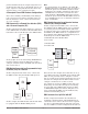
put has malfunctioned), the output assigned to serve as this function will come on. By default (factory settings), output 8 is assigned this function where any output of choice can be configured as such. A Conceptual View of RM Hardware Configurations Due to the scalability and flexibility in the RM system a user has several options available in the way that the hardware can be connected. Listed below are a few examples.
RM PID Controller RM Limit RM Access Slot C Slot C Slot C Slot E communicate with all modules (maximum 16 modules any combination with one Access module). Power Supply RM PID Controller RM Limit Slot C Slot C OIT Module Orientation The picture that follows represents one of several different RM modules. All of them will have four slots on the face (slot A, B, D, and E) and one on the bottom (slot C) not shown. All of these slots are not always used on all modules.
Getting Started Quickly Consider taking the following steps to quickly commission your control: • Wire and connect the power source to the control • Wire and connect input and output devices to the control • Power up the control and navigate to the Setup Page to configure inputs, outputs, alarms, etc... • Once the control is setup, navigate to the Operations Page to set limit and alarm set points.
Input Function Input Sensor EZ-ZONE RML-Limit Module - System Diagram 12 Limit Loops-Slots A, B, D 4-Form A Mechanical Relay Outputs Slot E Analog Input 1 through 12 None, Thermocouple, 2-Wire RTD (100, 1k), Thermistor (5k, 10K, 20k, 40k), Process (V, mV, mA) Output Function Limit Controller Slot A, B, D 4-Form A Mechanical Relay Outputs Output 7, 8, 9 and 10 5A Mechanical Relay Form A Note: Output 8 will always be the limit output regardless of Slot E options.
Input Function Input Sensor EZ-ZONE RML-Limit Module - System Diagram 6-Digital Inputs or Output Card in Slot D 1-Digital Input/2 Mechanical Relay Outputs Slot E Analog Input 1 through 12 None, Thermocouple, 2-Wire RTD (100, 1k), Thermistor (5k, 10K, 20k, 40k), Process (V, mV, mA) Output Function Limit Controller Slot A, B Digital Input 1, 2, 3, 4, 5 or 6 Switch contact or volts dc 6 - Digital Inputs / Outputs any combination Process Value Alarm Timer Special Output Function 1-4 Profile Event Output
2 Chapter 2: Install and Wire Dimensions As can be seen below the dimensions of the RM system will change slightly based on the type of connector used. Module Removal Clearance Standard Connectors 147.07 mm ( 5.8 in ) 75.08 mm ( 3.0 in ) 44.45 mm ( 1.75 in ) 101.60 mm ( 4.00 in ) 116.08 mm ( 4.57 in ) 150 51.56 mm ( 2.03 in ) Latch in open position 165 mm ( 6.50 in ) Module Removal Displacement Module Removal Clearance Straight Connectors 155 mm ( 6.10 in ) 75.08 mm ( 3.0 in ) 44.45 mm ( 1.
Chassis Mount Front View (Module Removed) - Screw Connection Pattern 58.67 mm (2.31 in) 17.53 mm (.69 in) 51.56 mm (2.03 in) 32.77 mm (1.29 in) 60.45 mm (2.38 in) 35.81 mm (1.41 in) 35.05 mm (1.38 in) 16.76 mm (.66 in) The view above is representative of the modular backplane without the module. Recommended chassis mount hardware: 1. #8 screw, 3/4" long 2. Torque to 10 -15 in-lb 3.
Power Supplies DSP60 DSP30 55.6 mm 2.189 in ++ - - L DC OK DSP60 N L N 5 6 6 14.20 mm 0.559 in 14.20 mm 0.559 in 5 Power Supply Specifications DSP100 DSP 30 56.8 mm 2.236 in 89.9 mm 3.539 in 49.00 mm 1.929 in 12 3 4 vout ADJ. 32.10 mm 1.264 in DC LO DC OK 5 6 14.20 mm 0.559 in 5 N 9.75 mm 0.384 in L 43.1 mm 1.697 in DSP100 91.00 mm 3.583 in 91.00 mm 3.583 in ++ - - 32.10 mm 1.264 in DC LO 91.00 mm 3.583 in 9.75 mm 0.384 in DSP30 1.697 in DC OK vout ADJ. 91.00 mm 3.
RML Installation and Removal on a DIN Rail Modular Backplane Connector The picture on the right shows the Modular Backplane Connector, both front and rear view. The rear view is bringing in to focus a metal clip. If the DIN rail is grounded the Modular Backplane Connector and the module connected to it will be also (recommended).
Module Removal To remove a module from the Modular Backplane Connector find the red tab protruding from the bottom of the module and pull back on it as shown to the right. While pulling back on the red tab the two mounting posts will release the module where the module can then be lifted up and out of the Modular Backplane Connector.
Wiring Limit Module (RMLx-xxxx-xxxx) Slot A Slot B Slot D Slot E Configuration Universal, RTD and Thermistor Inputs 1 -12 1-4 5-8 9 - 12 S1 R1 S2 R2 S3 R3 S4 R4 S5 R5 S6 R6 S7 R7 S8 R8 S9 R9 S10 R10 S11 R11 S12 R12 --- - - S_ (RTD), thermocouple -, volts -, mA - or thermistor R_ (RTD), thermocouple +, volts +, mA + or thermistor Universal/Thermistor Input Part # Digits 5, 6, 7 Input 1-4: RMLx-(5,6)xxx-xxxx Input 5-8: RMLx-x(5,6)xx-xxxx Input 9-12: RMLx-xx(5,6)x-xxxx Digital Inputs 1 - 6 ---
Digital Outputs 1 - 6 Slot A Slot B Slot D Slot E --- --- 1-6 --- - - - - - - B1 D1 D2 D3 D4 D5 D6 Z1 - - - Configuration Common open collector/ switched open collector/ switched open collector/ switched open collector/ switched open collector/ switched open collector/ switched Internal Supply Digital Outputs (DO) Part # Digit 7 Slot A: Option not valid Slot B: Option not valid Slot D: RMLx-xx(C)x-xxxx Slot E: Option not valid dc dc dc dc dc dc Power and Communications Slot C Configura
RML Module - Front View Standard Connector Slot D Slot E Slot A Slot B Slot C Slot C 98 99 power Watlow EZ-ZONE ® RML Module • 18 • Chapter 2 Install and Wire
RML System Isolation Blocks Mechanical Relay, Outputs Digital Inputs & Outputs Low-voltage Isolation Analog Input 1 - 12 (Ungrounded sensors only) Safety Isolation Safety Isolation Controller Power Supply 20.4 to 30.8VÎ (dc) 20.4 to 30.
Warning: Limit Module Wiring (RMLx-xxxx-xxxx) ç Use National Electric (NEC) or other country-specific standard wiring and safety practices when wiring and connecting this controller to a power source and to electrical sensors or peripheral devices. Failure to do so may result in damage to equipment and property, and/or injury or loss of life. Low Power RML- ALL Model Numbers • 20.4 to 30.
Warning: ç Inputs 1 through 12 RTD RML Part # Digits 5, 6, 7 Use National Electric (NEC) or other country-specific standard wiring and safety practices when wiring and connecting this controller to a power source and to electrical sensors or peripheral devices. Failure to do so may result in damage to equipment and property, and/or injury or loss of life. Slot A, B, D S_ • • • • R_ S_ R_ S_ Note: R_ Maximum wire size termination and torque rating: • 0.0507 to 3.
Warning: ç Process Inputs 1 through 12 RML Part # Digit 5, 6, 7 is 5 Use National Electric (NEC) or other country-specific standard wiring and safety practices when wiring and connecting this controller to a power source and to electrical sensors or peripheral devices. Failure to do so may result in damage to equipment and property, and/or injury or loss of life. + + Note: Maximum wire size termination and torque rating: • 0.0507 to 3.30 mm2 (30 to 12 AWG) single-wire termination or two 1.
Warning: ç Switched DC Wiring Example Using DO 1-6 Collector Outputs Use National Electric (NEC) or other country-specific standard wiring and safety practices when wiring and connecting this controller to a power source and to electrical sensors or peripheral devices. Failure to do so may result in damage to equipment and property, and/or injury or loss of life.
Warning: ç Output 1 - 4 and 7 - 10 Mechanical Relay, Form A Note: Maximum wire size termination and torque rating: • 0.0507 to 3.30 mm2 (30 to 12 AWG) single-wire termination or two 1.31 mm2 (16 AWG) • 0.8 Nm (7.0 in-lb.) torque Adjacent terminals may be labeled differently, depending on the model number. Note: To prevent damage to the controller, do not connect wires to unused terminals.
Warning: ç Use National Electric (NEC) or other country-specific standard wiring and safety practices when wiring and connecting this controller to a power source and to electrical sensors or peripheral devices. Failure to do so may result in damage to equipment and property, and/or injury or loss of life. Note: Note: To prevent damage to the controller, do not connect wires to unused terminals.
EZ-ZONE® RM to B&B Converter Model ULINXTM 485USBTB-2W USB to RS-485 Adapter using Standard Bus EZ ZONE R 1 D 98 99 CF CD CE CZ CW CY USB ULINX A TM USB Serial Conversion Model 485TB-2W B&B electronics E A B S M 1 9 2 10 3 11 4 12 5 13 6 14 7 15 8 16 B A(-) B(+) A(-) B(+) GND Slot C PC Software Protocol - Standard Bus EZ-Configurator Data format 38,400 baud 8 data bits no parity 1 start bit 1 stop bit D E Use twisted pair wires such as Cat 5 cabling.
Wiring a Serial EIA-485 Network Do not route network wires with power wires. Connect network wires in daisy-chain fashion when connecting multiple devices in a network. A termination resistor is required. Place a 120 Ω resistor across T+/R+ and T-/R- of the last controller on a network. Only one protocol per port is available at a time: either Modbus RTU or Standard Bus. A network using Watlow's Standard Bus and an RUI/Gate way.
Connecting and Wiring the Modules RML Module Connections The RML module can be installed as a stand-alone limit controller or can be interconnected on the DIN rail as shown below with other RM family modules. When modules are connected together as shown, power and communications are shared between modules over the modular backplane interconnection. Therefore, bringing the necessary power and communications wiring to any one connector in slot C is sufficient.
Remote User interface (RUI) Display Conventions Used in the Menu Pages Visual information from the control is displayed to the observer using a fairly standard 7 segment display. Due to the use of this technology, several characters displayed need some interpretation, see the list below: To better understand the menu pages that follow review the naming conventions used. When encountered throughout this document, the word "default" implies as shipped from the factory.
true throughout this document. By default the low order word contains the two low bytes of the 32-bit parameter. As an example, look in the Operations Page for the Process Value. Find the column identified in the header as Modbus and notice that it lists register 410. Because this parameter is a float it is actually represented by registers 410 (low order bytes) and 411 (high order bytes).
3 Chapter 3: Operations Pages Navigating the Operations Page To navigate to the Operations Page using the RUI, follow the steps below: the Up ¿ or Down ¯ key to select and then press the Advance Key ‰ to enter. 1. From the Home Page, press both the Up ¿ and Down ¯ keys for three seconds. [``Ai] will appear in the upper display and [oPEr] will appear in the lower display. 5. Press the Up ¿ or Down ¯ key to move through available menu prompts. 6.
RM Limit Module Display Parameter Name Description Range • Operations Page Default Modbus Relative Address CIP Class Instance Attribute hex (dec) Data Profibus Parameter Type Index ID & Read/ Write [``Ai] [oPEr] Analog Input Menu [``Ain] Analog Input (1 to 12) Process Value [ Ain] View the process value. -1,999.000 to 9,999.000°F or units -1,128.000 to 5,537.000°C ---- 410 [offset 90] 0x68 (104) 1 to 0x0C (12) 1 0 4001 float R [``pu;f] Analog Input (1 to 12) Filtered Process Value [ Pu.
RM Limit Module Parameter Name Description Display Range • Operations Page Default Modbus Relative Address CIP Class Instance Attribute hex (dec) Data Profibus Parameter Type Index ID & Read/ Write No Display Digital Input (1 to 6 and 9) Source Error View the state of this output.
RM Limit Module Parameter Name Description Display Range • Operations Page Default Modbus Relative Address CIP Class Instance Attribute hex (dec) Data Profibus Parameter Type Index ID & Read/ Write No Display Limit (1 to 12) Clear Request Clear limit once limit condition is cleared. Clear (0) No Change (255) ---- 1490 [offset 30] 0x70 (112) 1 to 0xC (12) 1 ---- 12001 uint RW No Display Limit (1 to 12) Status Reflects whether or not the limit is in a safe or failed mode..
RM Limit Module Display Parameter Name Description Range • Operations Page Default Modbus Relative Address CIP Class Instance Attribute hex (dec) Data Profibus Parameter Type Index ID & Read/ Write No Display Alarm (1 to 16) Clearable Read to determine if an alarm can be cleared No (59) Yes (106) None 2552 [offset 60] 0x6D (109) 1 to 0x10 (16) 0xC (12) ---- 9012 uint R No Display Alarm (1 to 16) Clear Request Write to this register to clear an alarm Clear (0) No Change (255) None 2554
RM Limit Module Parameter Name Description Display Range • Operations Page Default Modbus Relative Address CIP Class Instance Attribute hex (dec) Data Profibus Parameter Type Index ID & Read/ Write [`CPE] [oPEr] Compare Menu [`Su;A] [ Su.A] Compare (1 to 16) Source Value A View the value of Source A. -1,999.000 to 9,999.000°F or units -1,128.000 to 5,537.000°C 5922 [offset 40] 0x80 (128) 1 to 0x10 (16) 7 ---- 28007 float R [`Su;b] [ Su.
RM Limit Module Display Parameter Name Description Range No Display Timer (1 to 16) Running Read to determine if timer is running Off (62) On (63) No Display Timer (1 to 16) Output Error View reported cause for timer error • Operations Page Default ---- Modbus Relative Address CIP Class Instance Attribute hex (dec) Data Profibus Parameter Type Index ID & Read/ Write 7218 [offset 50] 0x83 (131) 1 to 0x10 (16) 0x0F (15) ---- 31015 uint R None (61) Open (65) Shorted (127) Measurement Error
RM Limit Module Parameter Name Description Display Range • Operations Page Default Modbus Relative Address CIP Class Instance Attribute hex (dec) Data Profibus Parameter Type Index ID & Read/ Write [`LgC] [oPEr] Logic Menu [`Su;A] [ Su.A] Logic (1 to 16) Source Value A View the value of Source A. [`off] Off (62) [``on] On (63) 4678 [offset 80] 0x7F (127) 1 to 0x10 (16) 0x19 (25) ---- 27025 uint R [`Su;b] [ Su.b] Logic (1 to 16) Source Value B View the value of Source B.
RM Limit Module Parameter Name Description Display No Display Logic (1 to 16) Output Error View reported cause for logic error Range • Operations Page Default Modbus Relative Address CIP Class Instance Attribute hex (dec) Data Profibus Parameter Type Index ID & Read/ Write None (61) Open (65) Shorted (127) Measurement Error (140) Bad Cal Data (139) Ambient Error (9) RTD Error (141) Fail (32) Math Error (1423) Not Sourced (246) Stale (1617) 4700 [offset 80] 0x7F (127) 1 to 0x10 (16) 0x24 (36)
RM Limit Module Display No Display Parameter Name Description Math (1 to 16) Output Error View reported cause for logic error Range • Operations Page Default None (61) Open (65) Shorted (127) Measurement Error (140) Bad Cal Data (139) Ambient Error (9) RTD Error (141) Fail (32) Math Error (1423) Not Sourced (246) Stale (1617) 3566 [offset 70] Note: Some values will be rounded off to fit in the four-character display. Full values can be read with other interfaces.
4 Chapter 4: Setup Pages Navigating the Setup Page To navigate to the Setup Page using the RUI, follow the steps below: 1. From the Home Page, press and hold both the Up ¿ and Down ¯ keys for six seconds. [``Ai] will appear in the upper display and [`Set] will appear in the lower display. Note: If keys are released when [OPEr] is displayed, press the Infinity Key ˆ or reset key to exit and repeat until [`Set] is displayed. 2. Press the Up ¿ or Down ¯ key to view available menus. 4.
[`Lnr] [`Set] Linearization Menu [```1] to [``16] [`Lnr] Linearization [``Fn] Function [SFn;A] Source Function A [`Si;A] Source Instance A [`S2;A] Source Zone A [Unit] Units [`ip;1] Input Point 1 [`op;1] Output Point 1 [`ip;2] Input Point 2 [`op;2] Output Point 2 [`ip;3] Input Point 1 [`op;3] Output Point 3 [`ip;4] Input Point 4 [`op;4] Output Point 4 [`ip;5] Input Point 5 [`op;5] Output Point 1 [`ip;6] Input Point 6 [`op;6] Output Point 6 [`ip;7] Input
RM Limit Module Display Parameter Name Description • Range Setup Page Default Modbus Relative Address CIP Class Instance Attribute hex (dec) Profibus Parameter Index ID Data Type & Read/ Write [``Ai] [`Set] Analog Input Menu [`Sen] [ SEn] Analog Input (1 to 12) Sensor Type Set the analog sensor type to match the device wired to this input. Note: There is no open-sensor detection for process inputs.
RM Limit Module Display Parameter Name Description Range Setup Page Default -100.0 to 1,000.0 Modbus Relative Address CIP Class Instance Attribute hex (dec) Profibus Parameter Index ID Data Type & Read/ Write 0.
RM Limit Module Display Parameter Name Description • Range Setup Page Default Modbus Relative Address CIP Class Instance Attribute hex (dec) Profibus Parameter Index ID Data Type & Read/ Write [`dio] [`Set] Digital Input/Output Menu [`dir] [ dir] Digital Input/Output (1 [OtPt] Output (68) to 8) [``in] Input Voltage (193) Direction [iCon] Input Dry Contact Set this function to operate (44) as an input or output.
RM Limit Module Parameter Name Description Display [`o;hi] [ o.hi] • Range Setup Page Default Digital Output (1 to 8) 0.0 to 100.0 High Power Scale The power output will never be greater than the value specified and will represent the value at which output scaling stops. Modbus Relative Address CIP Class Instance Attribute hex (dec) Profibus Parameter Index ID Data Type & Read/ Write 100.
RM Limit Module Parameter Name Description Display • Setup Page Range Default CIP Class Instance Attribute hex (dec) Profibus Parameter Index ID Data Type & Read/ Write 1 2212 [offset 20] 0x6E (110) 1 to 16 2 ---- 10002 uint RWES Action (1 to 16) 0 to 16 Source Zone A Set the zone of the function selected above. 0 2222 [offset 20] 0x6E (110) 1 to 16 7 ---- 10007 uint RWES Action (1 to 16) Active Level Set the action that will be considered a true state.
RM Limit Module Parameter Name Description Display • Setup Page Range Default [`S2;A] [ SZ.A] Limit (1 to 12) 0 or 16 Source Zone A Set the zone of the function selected above. 0 [`lCr] [ LCr] Limit (1 to 12) Limit Clear Clear the specified limit if limit condition no longer exists. [`Clr] Clear (129) [ignr] Ignore (204) Ignore [`l;st] [ L.St] Limit (1 to 12) Limit Status Current state of limit.
RM Limit Module Parameter Name Description Display • Range Setup Page Default Modbus Relative Address CIP Class Instance Attribute hex (dec) Profibus Parameter Index ID Data Type & Read/ Write [`o;Lo] [ o.Lo] Output (1 to 4 and 7 - 10) 0.0 to 100.0% Low Power Scale The power output will never be less than the value specified and will represent the value at which output scaling begins. 0.0% 1866 [offset 30] 0x6A (106) 1 to 10 9 ---- 6009 float RWES [`o;hi] [ o.
RM Limit Module Display Parameter Name Description • Setup Page Range Default [`A;Sd] [ A.Sd] Alarm (1 to 16) Sides Select which side or sides will trigger this alarm. [both] Both (13) [high] High (37) [LoW] Low (53) Both [`A;Lo] [ A.Lo] Alarm (1 to 16) Low Set Point If Alarm Type (Setup Page, Alarm Menu) is set to: process - set the process value that will trigger a low alarm. -1,999.000 to 9,999.000°F or units -1,128.000 to 5,537.000°C [`A;hi] [ A.
RM Limit Module Display Parameter Name Description • Setup Page Range Default Modbus Relative Address CIP Class Instance Attribute hex (dec) Profibus Parameter Index ID Data Type & Read/ Write [A;sir] [A.Sir] Alarm (1 to 16) Silence Request Write to this register to silence an alarm Ignore Silence Ignore ---- ---- ---- ---- ---- [`A;st] [ A.
RM Limit Module Display Parameter Name Description • Range Setup Page Default Modbus Relative Address CIP Class Instance Attribute hex (dec) Profibus Parameter Index ID Data Type & Read/ Write [`iP;1] [ ip.1] Linearization (1 to 16) Input Point 1 Set the value that will be mapped to output 1. -1,999.000 to 9,999.000 0.0 8004 0x86 (134) [offset 70] 1 to 0x10 (16) 8 157 34008 float RWES [`oP;1] [ op.1] Linearization (1 to 16) Output Point 1 Set the value that will be mapped to input 1.
RM Limit Module Display Parameter Name Description • Range Setup Page Default Modbus Relative Address CIP Class Instance Attribute hex (dec) Profibus Parameter Index ID Data Type & Read/ Write [`oP;7] [ op.7] Linearization (1 to 16) Output Point 7 Set the value that will be mapped to input 7. -1,999.000 to 9,999.000 6.0 8036 0x86 (134) [offset 70] 1 to 0x10 (16) 0x18 (24) 170 34024 float RWES [`iP;8] [ ip.
RM Limit Module Display Parameter Name Description • Range Setup Page Default Modbus Relative Address CIP Class Instance Attribute hex (dec) Profibus Parameter Index ID Data Type & Read/ Write [SFn;A] [SFn.A] Compare (1 to 16) Source Function A Set the type of function that will be used for this source.
RM Limit Module Parameter Name Description Display • Range Setup Page Default Modbus Relative Address CIP Class Instance Attribute hex (dec) Profibus Parameter Index ID Data Type & Read/ Write [tMr] [`Set] Timer Menu 7206 0x83 (131) [offset 50] 1 to 16 9 223 31009 uint RWES None [nonE] None (61) [ALM] Alarm Reset (6) [`CPE] Compare (230) [`Ctr] Counter (231) [`dio] Digital I/O (1142) [Ent;A] Profile Event Out A (233) [Ent;b] Profile Event Out B (234) [Ent;C] Profile Event Out C (235) [Ent;d]
RM Limit Module Display Parameter Name Description • Range Setup Page Default Modbus Relative Address CIP Class Instance Attribute hex (dec) Profibus Parameter Index ID Data Type & Read/ Write [SFn;B] [SFn.b] Timer (1 to 16) Source Function B Set the type of function that will be used to reset a retentive timer (reset signal).
RM Limit Module Display Parameter Name Description • Range Setup Page Default Modbus Relative Address CIP Class Instance Attribute hex (dec) Profibus Parameter Index ID Data Type & Read/ Write [`Ctr] [`Set] Counter Menu [``Fn] [ Fn] Counter (1 to 16) [``UP] Up (1456) Function [``dn] Down (1457) Set whether the counter increments or decrements the count value. Decrementing 0 returns 9,999. Incrementing 9,999 returns 0.
RM Limit Module Display Parameter Name Description • Range Setup Page Default Modbus Relative Address CIP Class Instance Attribute hex (dec) Profibus Parameter Index ID Data Type & Read/ Write [SFn;B] [SFn.b] Counter (1 to 16) Source Function B Set the type of function that will be used for the counter load signal.
RM Limit Module Parameter Name Description Display • Range Setup Page Default Modbus Relative Address CIP Class Instance Attribute hex (dec) Profibus Parameter Index ID Data Type & Read/ Write [`LgC] [`Set] Logic Menu 4694 0x7F (127) [offset 80] 1 to 16 0x21 (33) 235 27033 uint RWES None [[nonE] None (61) [ALM] Alarm Reset (6) [`CPE] Compare (230) [`Ctr] Counter (231) [`dio] Digital I/O (1142) [Ent;A] Profile Event Out A (233) [Ent;b] Profile Event Out B (234) [Ent;C] Profile Event Out C (235
RM Limit Module Display Parameter Name Description • Range [`S2;A] [ SZ.A] Logic (1 to 16) 0 to 16 Source Zone A Set the zone of the function selected above. [SFn;b] [SFn.b] Logic (1 to 16) Source B Function Set the type of function that will be used for this source. [`Si;B] [ Si.b] Logic (1 to 16) Source Instance B Set the instance of the function selected above. {`S2;B] [ SZ.
RM Limit Module Display Parameter Name Description • Range Setup Page Default Modbus Relative Address CIP Class Instance Attribute hex (dec) Profibus Parameter Index ID Data Type & Read/ Write [SFn;C] [SFn.C] Logic (1 to 16) Source Function C Set the type of function that will be used for this source.
RM Limit Module Display Parameter Name Description • Range Setup Page Default Modbus Relative Address CIP Class Instance Attribute hex (dec) Profibus Parameter Index ID Data Type & Read/ Write [SFn;D] [SFn.d] Logic (1 to 16) Source Function D Set the type of function that will be used for this source.
RM Limit Module Display Parameter Name Description • Range Setup Page Default Modbus Relative Address CIP Class Instance Attribute hex (dec) Profibus Parameter Index ID Data Type & Read/ Write [SFn;E] [SFn.E] Logic (1 to 16) Source Function E Set the type of function that will be used for this source.
RM Limit Module Display Parameter Name Description [SFn;F] Logic (1 to 16) [ SFn.F] Source Function F Set the type of function that will be used for this source.
RM Limit Module Display Parameter Name Description • Range Setup Page Default Modbus Relative Address CIP Class Instance Attribute hex (dec) Profibus Parameter Index ID Data Type & Read/ Write [SFn;g] [SFn.g] Logic (1 to 16) Source Function G Set the type of function that will be used for this source.
RM Limit Module Display Parameter Name Description [SFn;h] Logic (1 to 16) [ SFn.h] Source Function H Set the type of function that will be used for this source.
RM Limit Module Parameter Name Description Display • Setup Page Range Default Modbus Relative Address CIP Class Instance Attribute hex (dec) Profibus Parameter Index ID Data Type & Read/ Write [MAt] [`Set] Math Menu [``Fn] [ Fn] Math (1 to 16) Function Set the operator that will be applied to the sources.
RM Limit Module Display Parameter Name Description • Range Setup Page Default Modbus Relative Address CIP Class Instance Attribute hex (dec) Profibus Parameter Index ID Data Type & Read/ Write [SFn;b;] [SFn.b] Math (1 to 16) Source Function B Set the type of function that will be used for this source.
RM Limit Module Display Parameter Name Description • Range Setup Page Default Modbus Relative Address CIP Class Instance Attribute hex (dec) Profibus Parameter Index ID Data Type & Read/ Write [SFn;D] [SFn.d] Math (1 to 16) Source Function D Set the type of function that will be used for this source.
RM Limit Module Display Parameter Name Description • Range [`s2;E] [ SZ.E] Math (1 to 16) 0 to 16 Source Zone E Set the zone of the function selected above. [`S;Lo] [ S.Lo] Math (1 to16) Input Scale Low This value will correspond to Output Range Low. [`S;hi] [ S.hi] Setup Page Default Modbus Relative Address CIP Class Instance Attribute hex (dec) Profibus Parameter Index ID Data Type & Read/ Write 0 3538 [offset 70] 0x7D (125) 1 to 16 0xF (15) ---- 25015 uint RWES -1,999.000 to 9,999.
RM Limit Module Parameter Name Description Display • Setup Page Range Default Modbus Relative Address CIP Class Instance Attribute hex (dec) Profibus Parameter Index ID Data Type & Read/ Write [`Dig] [ dig] Variable (1 to 16) Digital Set the variable's value. [`oFF] Off (62) [``on] On (63) Off 9112 0x66 (102) [offset 20] 1 to 0x10 (16) 2 211 2002 uint RWES [anLg] [AnLg] Variable (1 to 16) Analog Set the variable's value. -1,999.000 to 9,999.000 0.
RM Limit Module Display Parameter Name Description • Range [M;hL] [M.hL] Communications [hiLo] Word High Low Modbus Word Order (1330) Select the word order of [Lohi] Word Low High the two 16-bit words in the (1331) floating-point values. [`C_F] [ C_F] Communications Comm Units Select which scale to use for temperature over comms. [`nU;S] [ nV.S] Communications (1) [`yes] Yes (106) Non-volatile Save [``no] No (59) If set to Yes all values written to the control will be saved in EEPROM.
5 Chapter 5: Factory Pages Navigating the Factory Page To navigate to the Factory Page using the RUI, follow the steps below: 5. Press the Up ¿ or Down ¯ key to move through available menu prompts. 1. From the Home Page, press and hold both the Advance ‰ and Infinity ˆ keys for six seconds. 6. Press the Infinity Key ˆ to move backwards through the levels: parameter to submenu; submenu to menu; menu to Home Page. 2. Press the Up ¿ or Down ¯ key to view available menus. 7.
RM Limit Module Display Parameter Name Description • Factory Page Modbus Relative Address CIP Class Instance Attribute hex (dec) Data Profibus Parameter Type Index ID & Read/ Write Range Default [nonE] None (61) [`Pro] Process (75) [`i;CA] Input Calibration Offset (1196) [`C_F] Display Units (156) [USr;r] User Restore Set (227) [`A;Lo] Alarm Low Set Point (42) [`A;hi] Alarm High Set Point (78) [`A;hy] Alarm Hysteresis (97) [`LL;S] Limit Low Set Point (181) [`Lh;S] Limit High Set Point (182) [`L;hy]
RM Limit Module Display Parameter Name Description • Range Factory Page Default Modbus Relative Address CIP Class Instance Attribute hex (dec) Data Profibus Parameter Type Index ID & Read/ Write [SLoC] [SLoC] Security Setting Write Security Set the write security clearance level. The user can access the selected level and all lower levels. If the Set Lockout Security level is higher than the Read Lockout Security, the Read Lockout Security level takes priority.
RM Limit Module Display Parameter Name Description • Range Factory Page Default Modbus Relative Address CIP Class Instance Attribute hex (dec) Data Profibus Parameter Type Index ID & Read/ Write [diAg] [FCty] Diagnostics Menu [``Pn] [ Pn] Diagnostics Menu Part Number Display this controller's part number. 24 ---- 0x65 (101) 1 9 66 1009 uint RWE No Display Diagnostics Menu Device Name Read the hardware ID.
RM Limit Module Display [ELi;S] [ELi.S] Parameter Name Description Calibration Menu (1 to 12) Electrical Input Slope Adjust this value to calibrate the slope of the input value. • Range Factory Page Default -1,999.000 to 9,999.000 1.0 Note: Some values will be rounded off to fit in the four-character display. Full values can be read with another interface. If there is only one instance of a menu, no submenus will appear.
6 Chapter 6: Features Saving and Restoring User Settings. . . . . . . . . . . . . . . . . . . . . . . . . . 79 Module Limit . . . . . . . . . . . . . . . . . . . . . . . . . . . . . . . . . . . . . . . . . 79 Inputs . . . . . . . . . . . . . . . . . . . . . . . . . . . . . . . . . . . . . . . . . . . . . . 79 Calibration Offset . . . . . . . . . . . . . . . . . . . . . . . .
Saving and Restoring User Settings Inputs Recording setup and operations parameter settings for future reference is very important. If you unintentionally change these, you will need to program the correct settings back into the controller to return the equipment to operational condition. After you program the controller and verify proper operation, use User Save Set [USr;S] (Setup Page, Global Menu) to save the settings into either of two files in a special section of memory.
Follow these steps for an RTD input: 1. Measure the low source resistance to ensure it is accurate. Connect the low source resistance to the input you are calibrating. 2. Read the value of Electrical Measurement [`Mu] (Factory Page, Calibration Menu) for that input. 3. Calculate the offset value by subtracting this value from the low source resistance. 4. Set Electrical Input Offset [ELi;o] (Factory Page, Calibration Menu) for this input to the offset value. 5.
Scale low and high low values do not have to match the bounds of the measurement range. These along with range low and high provide for process scaling and can include values not measureable by the controller. Regardless of scaling values, the measured value will be constrained by the electrical measurements of the hardware. Select the low and high values with Scale Low [`S;Lo] and Scale High [`S;hi]. Select the displayed range with Range Low [`r;Lo] and Range High [`r;hi] (Setup Page, Analog Input Menu).
condition has passed. It can only be deactivated by the user. An active message, such as an alarm message, will cause the RUI display to toggle between the normal settings and the active message in the upper display and [Attn] in the lower display. Push the Advance Key ‰ to display [ignr] in the upper display and the message source in the lower display. Use the Up ¿ or Down ¯ keys to scroll through possible responses, such as Clear [`CLr] or Silence [`SiL].
Lockout Security [rLoC] to 1 and Set Lockout Security [SLoC] to 5. In the Factory Page, Lockout Menu, set Lock Operations Page [LoC;O] to 2 and Lock Profiling Page [LoC;P] to 3.
Note: If Password Security (Password Enabled [ pas ; e ] is On) is enabled the two prompts mentioned below in the first step will not be visible. If unknown, call the individual or company that originally setup the control. 1. Acquire either the User Password [ pas ; u ] or the Administrator Password [ pas ; a ] . 2. Push the Advance ‰ key one time where the Code [Cod e] prompt will be visible. Note: a.
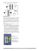
Software Configuration Using EZ-ZONE® Configurator Software To enable a user to configure the RML control using a personal computer (PC), Watlow has provided free software for your use. If you have not yet obtained a copy of this software insert the CD (Controller Support Tools) into your CD drive and install the software.
In the previous screen shot the RML is shown highlighted (address 11) to bring greater clarity to the control in focus. Any EZ-ZONE device on the network will appear in this window and would be available for the purpose of configuration or monitoring. After clicking on the control of choice simply click the next button once again. The next screen appears below. eter will appear in the center column.
Although the RML control now contains the configuration (because the previous discussion focused on doing the configuration on-line) it is suggested that after the configuration process is completed that the user save this file on the PC for future use. If for some reason someone inadvertently changed a setting without understanding the impact it would be easy and perhaps faster to download a saved configuration back to the control versus trying to figure out what was changed.
Function Block Descriptions Alarm Function Each of the next several pages graphically shows each of the RML function blocks. Note that as you view each you will find text that is black and text that appears gray. The gray text represents inputs that are not currently available based on the functions defined use (red text). For instance, when the defined use of the Analog Input function is set for RTD, TC Linearization will appear gray.
Analog Input Function A Al Al A Al larm arm arm larm Al Al Al Al a a rm L H Si C a A a a r Al Cont m H Ala Ala rm L rm B rm S larm De ow igh lence lear arm ro ys rm rm at lo il D la Se Se R R e t t Ty l Loo teres Log Sid chin ckin ncin ispl y Tim Poi Poi eque eque pe p is ic es g g g ay e nt nt st st Alarm Source Alarm Source Instance Alarm Source Zone Alarm Source Error Note: This Function configures and connects physical inputs to internal functions.
Compare Function P Inp Pr roces C oce s ut D Ca lear T TC ss Err her Resi Er isp lib L L s m r E o l i R t Se ne or ay rati atch S Sc R a rr r L is an ns ar or iza U cale ale H ange nge H or En ow V tor C ce R F Latc Prec on O Req Ty tio n Lo ig Lo ig ab al ur an ilte hin isi ffs ue pe n its w h w h le ue ve ge r g on et st Analog Input Analog Input Off An error, when read, can indicate any of the following: None, Open, Shorted, Measurement Error, Bad Cal Data, Ambient Error, RTD Error, Fail, Math Error
Er ror Fu Tol Han nc era dli tio nc ng n e Source Function A Source Instance A Source Zone A Source Error A Source Function B Source Instance B Source Zone B Source Error B Er ro Fu To r Ha nc ler n tio an dlin n ce g Source Function A Source Instance A Source Zone A Source Error A Source Value A Source Value B Compare Greater Than Source Value A Source Value B Compare Not Equal To Source Function B Source Instance B Source Zone B Source Error B Output Value Error Output Value Error A not equal
Counter Function Function counts up or down from Load Value and produces Output Value = On when Count = Target Value. Note: Count value clears on power loss. Load Value restored on power up. Counter Operation: Whenever a prescribed clock transition occurs without an error on source B the count will be equal to the Load Value. If Function is an Up Counter: Whenever a prescribed clock transition occurs without an error on Source A the count will increment by +1.
Digital Input/Output Function Ou Ou tp tp O ut ut Ou utp Low High tp ut P P Di ut C Tim owe owe rec on e r S r S tio tro Bas ca ca n l e le le Note: Input Value is passed to either profile event inputs or action function blocks. Output Value determined by Source A and Digital Output Function.
Limit Function Linearization Function This function uses a dedicated input and the output will change state when Source A exceeds limit set points. The limit, when tripped, must be manually cleared to reset the output and clear the message. The Analog Input and mechanical relay output are dedicated to each limit loop and are located in same module. This function will take an analog Source A and relinearize using a 10-point offset, then add Offset and produce an Output Value.
Logic Function O Inp Outp Inp Outp Inp Outp Inp Outp Inp Outp Inp Outp In Outp Inp Outp Inp Outp Inpu utpu ut ut ut ut ut ut ut ut ut ut ut ut put ut ut ut ut ut t P t P Po Po Poi Poi Po Po Po Po Po Po Po Po Po Po Po Po Po Po oin oin O U i i i i i i i i i i i i i i i tio ni nt nt nt nt nt nt nt nt nt nt nt nt int nt nt nt nt nt t 1 t 1 ffs n ts 1 1 2 2 3 3 4 4 5 5 6 6 7 7 8 8 9 9 0 0 et Fu nc Source Function A Source Instance A Source Zone A Source Error A Linearization Interpolated Error Handling Fun
[`LgC] Logic Menu [`SEt] Setup Page Function [``fn] Function : Off, AND, OR, Equal To, NAND, NOR, Not Equal To, Latch, RS Flip Flop Source Function A Source Instance A Source Zone A Source Error A [SFn;A] Source Function A : None, Alarm, Compare, Counter, Digital I/O, Profile Event Out A to H, Function Key, Limit, Logic, Special Function Output 1 to 4, Timer, Variable [`Si;A] Source Instance A : 1 to 250 [`S2;A] Source Zone A : 0 to 16 [SFn;b] Source Function B : None, Alarm, Compare, Counter, Digital I
Function Source Function A Source Instance A Source Zone A Source Error A Error Handling Source Value C Source Value D Source Function C Source Instance C Source Zone C Source Error C Source Value G Source Function E Source Instance E Source Zone E Source Error E Source Function A Source Instance A Source Zone A Source Error A Source Value A Source Value B Source Function B Source Instance B Source Zone B Source Error B Source Function D Source Instance D Source Zone D Source Error D Function Sou
Function Source Function A Source Instance A Source Zone A Source Error A Source Function B Source Instance B Source Zone B Source Error B Source Function C Source Instance C Source Zone C Source Error C Source Function D Source Instance D Source Zone D Source Error D Source Function E Source Instance E Source Zone E Source Error E Error Handling Function Source Value A Source Function A Source Instance A Source Zone A Source Error A Source Value B Source Value C Source Value D Source Value E Source Va
P A R res lt Fu Scal Scal Rang ange sure itude e nc e L H e L H U U Fi Of tio n n l n ow igh ow igh its its ter fset Source Function A Source Instance A Source Zone A Source Error A Source Function A Source Instance A Source Zone A Source Error A Source Value A Source Value B Source Value C Source Function B Source Instance B Source Zone B Source Error B Source Function B Source Instance B Source Zone B Source Error B Source Value D Source Value E Source Function C Source Instance C Source Zone C Sou
P A R res lt Fu Scal Scal Rang ange sure itude nc e L e H e L H U U Fi Of tio n n l n ow igh ow igh its its ter fset P A R res lt Fu Sca Scal Rang ange sure itude nc le L e H e L H U U Fi Of tio o ig o ig nit ni lte fse n w h w h t r s ts Source Function A Source Instance A Source Zone A Source Error A Source Function A Source Instance A Source Zone A Source Error A Source Value A Source Value B Source Value C Source Function B Source Instance B Source Zone B Source Error B Source Function B Source In
P A R res lt Fu Sca Scal Rang ange sure itude nc le L e H e L H U U Fi Of tio o ig o ig nit ni lte fse n w h w h t r s ts Source Function A Source Instance A Source Zone A Source Error A Source Function B Source Instance B Source Zone B Source Error B Source Function C Source Instance C Source Zone C Source Error C Source Function D Source Instance D Source Zone D Source Error D P A R res lt Fu Scal Scal Rang ange sure itude nc e L e H e L H U U Fi Of tio n n l n ow igh ow igh its its ter fset Source Fun
P A R res lt Fu Scal Scal Rang ange sure itude e nc e L H e L H U U Fi Of tio n n l n ow igh ow igh its its ter fset P A R res lt Fu Sca Scal Rang ange sure itude nc le L e H e L H U U Fi Of tio o ig o ig nit ni lte fse n w h w h t r s ts Source Function A Source Instance A Source Zone A Source Error A Source Value B Source Function D Source Instance D Source Zone D Source Error D Source Function B Source Instance B Source Zone B Source Error B Source Value C Source Function B Source Instance B Sourc
Output Function P A R res lt Fu Sca Scal Rang ange sure itude nc le L e H e L H U U Fi Of tio o ig o ig nit ni lte fse n w h w h t r s ts Source Function A Source Instance A Source Zone A Source Error A Source Function B Source Instance B Source Zone B Source Error B Source Function C Source Instance C Source Zone C Source Error C Source Function D Source Instance D Source Zone D Source Error D Source Function E Source Instance E Source Zone E Source Error E This function configures and connects physical
Security Function Ou Out tp pu O ut t H Ou utp Low igh tpu ut T Po Po t C im we wer on e B r Sc Sc tro as al al e e e l Note: Set on a Zone by Zone basis affecting any access using Standard Bus communications. Does not affect field protocols.. This is independent of the RUI Security Setting. If the Password is enabled, the user must enter the Password to get to menus that have been blocked due to lock level settings.
Timer Function So ur Sour ce ce Ac Ac Ac ti t tiv Fu ve S ive S e nc tat ta tio e A te Tim Leve B n e l An error, when read, can indicate any of the following: None, Open, Shorted, Measurement Error, Bad Cal Data, Ambient Error, RTD Error, Fail, Math Error, Not Sourced, Stale So ur Sour ce ce Ac A ti ct Ac tiv Fu ve S ive S e nc tat ta tio e A te Tim Leve B n e l Source Function A Source Instance A Source Zone A Source Error A Source Function B Source Instance B Source Zone B Source Error B Source Fu
So ur Sour ce ce Ac Ac ti ti Fu ve S ve S nc tat tat tio e A e B n Source Function A Source Instance A Source Zone A Source Error A Ac tiv e Tim Lev e el Source Value A Source Value B Elapsed Time Source Function B Source Instance B Source Zone B Source Error B Output Value Error Timer On Pulse An On Pulse Timer is used to produce an output pulse of a constant duration. It can be used as a minimum on time for compressor control or other devices that do not want excessive cycling.
So ur Sour ce ce Ac Ac ti t Ac tiv Fu ve S ive S e nc tat ta tio e A te Tim Lev B n e el Source Function A Source Instance A Source Zone A Source Error A Source Value A Source Value B Elapsed Time Source Function B Source Instance B Source Zone B Source Error B Output Value Error Timer Delay A delay timer is used to cause a delaying action. The delay can be made to happen on either the leading or trailing edge.
So ur Sour ce ce Ac Ac ti t Ac tiv Fu ve S ive S e nc tat ta tio e A te Tim Lev B n e el Source Function A Source Instance A Source Zone A Source Error A Source Value A Source Value B Elapsed Time Source Function B Source Instance B Source Zone B Source Error B Output Value Error Timer One Shot The One Shot timer functions like a simple oven timer. The time value gets set by the user and it counts down to zero without retaining the original time (hence the name one-shot).
So ur Sour ce ce Ac A Ac ti ct tiv Fu ve S ive S e nc tat ta tio e A te Tim Leve n B e l Source Function A Source Instance A Source Zone A Source Error A Source Value A Source Value B Elapsed Time Source Function B Source Instance B Source Zone B Source Error B Output Value Error Timer Retentive A retentive timer is used to keep track of how much time something has been in a particular state.
Variable Function Di An git al Da al og Va Va ta Ty Un lue lue pe its This function simply passes the stored value to its output. An error, when read, can indicate any of the following: None, Open, Shorted, Measurement Error, Bad Cal Data, Ambient Error, RTD Error, Fail, Math Error, Not Sourced, Stale Output Value A variable function block is used to store a user supplied value and provide a source input to another function block with that value.
7 Chapter 7: Appendix Modbus - Programmable Memory Blocks The Modbus assembly contains 40 pointers to the parameters of your choosing starting at Modbus register 40 (shown on the following page). The pointers are 32-bits long so are stored in two sequential registers. As an example, if we want to move an alias to the analog input of the RML (register 410) into register 40, we perform a multiple write command (0x10 function) of 410 into register 40 and 411 into register 41 as a single multi-write command.
Assembly Pointer Registers and Assembly Working Registers Pointer Addresses Working Addresses Pointer Addresses Working Addresses 40 & 41 200 & 201 120 & 121 280 & 281 42 & 43 202 & 203 122 & 123 282 & 283 44 & 45 204 & 205 124 & 125 284 & 285 46 & 47 206 & 207 126 & 127 286 & 287 48 & 49 208 & 209 128 & 129 288 & 289 50 & 51 210 & 211 130 & 131 290 & 291 52 & 53 212 & 213 132 & 133 292 & 293 54 & 55 214 & 215 134 & 135 294 & 295 56 & 57 216 & 217 136 & 137 296 & 297
Modbus Default Assembly Structure 40-119 Assembly Definition Addresses Default Pointers Assembly Working Addresses Registers 40 & 41 Registers 200 & 201 Pointer 1 = 0 & 1 Hardware ID Registers 42 & 43 Pointer 2 = 0 & 1 Hardware ID Registers 44 & 45 Pointer 3 = 0 & 1 Hardware ID Registers 46 & 47 Pointer 4 = 0 & 1 Hardware ID Registers 48 & 49 Pointer 5 = 0 & 1 Hardware ID Registers 50 & 51 Pointer 6 = 0 & 1 Hardware ID Registers 52 & 53 Pointer 7 = 0 & 1 Hardware ID Registers 54 & 55 Pointer 8 = 0
Modbus Default Assembly Structure 120-199 Assembly Pointer Registers Default Pointers Registers 120 & 121 Pointer 31 = 0 & 1 Hardware ID Registers 122 & 123 Pointer 32 = 0 & 1 Hardware ID Registers 124 & 125 Pointer 33 = 0 & 1 Hardware ID Registers 126 & 127 Pointer 34 = 0 & 1 Hardware ID Registers 128 & 129 Pointer 35 = 0 & 1 Hardware ID Registers 130 & 131 Pointer 36 = 0 & 1 Hardware ID Registers 132 & 133 Pointer 37 = 0 & 1 Hardware ID Registers 134 & 135 Pointer 38 = 0 & 1 Hardware ID Re
Troubleshooting Alarms, Errors and Module Issues Indication Description Possible Cause(s) Alarm won’t clear or reset Alarm will not clear or reset • Alarm latching is active with keypad or digital input • Alarm set to incorrect output Alarm won’t occur Alarm will not activate output • Alarm silencing is active • Alarm blocking is active • Alarm is set to incorrect output Corrective Action • Reset alarm when process is within range or disable latching • Set output to correct alarm source instance • A
Indication Description Possible Cause(s) Corrective Action No Serial Communication Cannot establish serial communications with the controller • Address parameter incorrect • Incorrect protocol selected • Baud rate incorrect • Parity incorrect • Wiring error • EIA-485 converter issue • Incorrect computer or PLC communications port • Incorrect software setup • Wires routed with power cables • Termination resistor may be required • Set unique addresses on network • Match protocol between devices • Match
RML Specifications Connector Dimension “A” (mm/in.) Line Voltage/Power Standard 148 (5.80) • 20.4 to 30.8Vı (ac/dc), 50/60Hz, ±5 percent • Any external power supply used should comply with a class 2 or SELV rating. (See specific module specification listing for maximum VA power consumption) • Data retention upon power failure via nonvolatile memory • Compliant with Semi F47-0200, Figure R1-1 voltage sag requirements Straight 155 (6.
Digital Input Operating Range Input Type Range Low Range High • Update rate 10Hz • DC voltage - Max. input 36V at 3mA - Min. high state 3V at 0.25mA - Max.
EZ-ZONE Rail-Mount Limit Module Ordering Information Limit module requires a Class 2 or SELV power supply 20.4 to 30.8 V ~(ac) / port provided for configuration with EZ-ZONE Configurator software.
Index [`A;bL] Alarm Blocking 50, 82 [AC;LF] AC Line Frequency 71 [A;Clr] Alarm Clear Request 50 [`ACt] Action Menu 33, 46 [A;dSP] Alarm Display 50 [`A;hi] Alarm High Set Point 34, 50, 51, 81 [`A;hy] Alarm Hysteresis 49, 81 [``Ai] Analog Input Menu 32, 43 [`A;iS] Alarm Source Instance 49 [`A;LA] Alarm Latching 50, 82 [`A;Lg] Alarm Logic 49 [ALM] Alarm Menu 34, 49 [`A;Lo] Alarm Low Set Point 34, 50, 81 [`A;Sd] Alarm Sides 50 [`A;Si] Alarm Silencing 50, 82 [A;sir] Alarm Silence Request 51 [`A;st] Alarm State 5
Action Menu 46 Alarm Menu 49 Analog Input Menu 43 Communications Menu 71 Compare Menu 53 Counter Menu 57 Digital Input/Output Menu 45 Global Menu 71 Limit Menu 47 Linearization Menu 51 Logic Menu 59 Math Menu 67 Output Menu 48 Timer Menu 55 Variable Menu 70 Counter Menu 37, 57 current measurement 117 current sensing 82 Current Sensing 82 Custom Function 92 Custom Setup Menu 74 D Date of Manufacture 76 Decimal 44 Dewpoint 67 Diagnostics Menu 76 Digital Input Function 5 Digital Input/Output Menu 32, 45 digit
Source 49 Specifications 117 standard connector, all modules 18 State 51 System Security 83 T Ten Point Linearization 81 Time Base 45, 48 Timer Function 105 Timer Menu 36, 55 tuning the PID parameters 79 Type 49 U User Password 75 User Restore Set 71, 79 User Save Set 71, 79 Using EZ-ZONE® Configurator Software 85 using the software 82 V Variable Function 110 Variable Menu 70 W wiring Modbus RTU or standard bus EIA485 communications 25 output 1 mechanical relay, form C 24 wiring a network 27, 28 wiring
Declaration of Conformity EZ Zone Series RM WATLOW an ISO 9001 approved facility since 1996. 1241 Bundy Blvd. Winona, MN 55987 USA Declares that the following Series RM (Rail Mount) products: RM followed by additional letters or numbers describing use of up to four module Model Numbers: options of various inputs and outputs or communications.
How to Reach Us Corporate Headquarters Watlow Electric Manufacturing Company 12001 Lackland Road St. Louis, MO 63146 Sales: 1-800-WATLOW2 Manufacturing Support: 1-800-4WATLOW Email: info@watlow.com Website: www.watlow.com From outside the USA and Canada: Tel: +1 (314) 878-4600 Fax: +1 (314) 878-6814 Latin America Watlow de México S.A. de C.V. Av. Fundición No. 5 Col. Parques Industriales Querétaro, Qro. CP-76130 Mexico Tel: +52 442 217-6235 Fax: +52 442 217-6403 Europe Watlow France Tour d'Asnières.