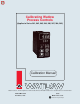
Calibrating Watlow Process Controls (Applies to Series 981, 982, 983, 984, 986, 987, 988, 989) Calibration Manual Watlow Controls, 1241 Bundy Blvd., P.O. Box 5580, Winona, MN 55987-5580, Phone: 507/454-5300, Fax: 507/452-4507 W988-CM10-9345 November, 1993 $5.00 Made in the U.S.A.
Contents Page Description Calibrating Your Watlow Process Control 3 3 4 6 7 7 7 7 The Factory (Fcty) Menus Entering the Fcty Prompt Diagnostics Menu Calibration Menu Calibration Restore Prompt The dFL Prompt Input Calibration Output Calibration Calibration Procedures 8 9 10 11 12 13 14 14 15 16 17 17 2 Low Gain Thermocouple Input High Gain Thermocouple Input RTD Input mA Process Input VDC Process Input mVDC Process Input Slidewire Feedback Input Current Transformer Input mA Process Output 1 and 2 VDC
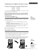
Calibrating Your Watlow Process Control Menus/Prompts This manual is a supplement to the Series 981/982 and 988/989 User’s Manual. The calibration procedures within this manual pertain to the following controls: Series 981 Series 986 Series 982 Series 987 Series 983 Series 988 Series 984 Series 989 Use in conjunction with the appropriate user’s manual. From this point on, 988 will be used in place of the above listed models.
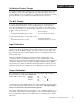
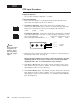
Diagnostics Diagnostics Menu The Diagnostics menu (diAg) contains specific information for each control. This menu is for factory use only, but can be accessed for viewing or technical assistance. • At the Fcty prompt, press the Up or Down key to advance the upper display to the diAg prompt. See below. Use the Mode key to advance through this menu. Do not enter any readings here; make photocopies instead.
When contacting the factory for technical assistance, make sure you have the information documented from the following prompts. All prompts in this menu are read only. Diagnostics Date: This prompt represents the date the final control test was performed. The first two numbers are the week (01 through 52), and the last two numbers are the year. DAtE Software Revision: Signifies the control software revision. SOFt Serial Number: Represents the control serial number.
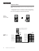
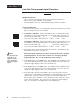
CAL Menu Calibration Menu Enter the Factory menu again by pressing the Up and Down keys simultaneously for three seconds to enter the Setup menu, and an additional three seconds to enter the Factory menu. • At the Fcty prompt, press the Up or Down key to advance to the upper display to the CAL prompt.
rSt/dFL Prompts Calibration Restore Prompt If you make a mistake while calibrating your control, the rSt prompt near the end of the calibration menu restores the original factory calibration settings. At the rSt prompt, simply press the Up or Down key to change the upper display to read YES; press the Mode key. The original factory calibration values are restored.
Low Gain T/C Low Gain Thermocouple Input Procedure For all thermocouple inputs excluding Type R, S and B Equipment Required • Type J reference compensator with reference junction at 32°F/0°C, or Type J thermocouple calibrator set at 32°F/0°C • Precision millivolt source, 0 - 50mV minimum range, 0.01mV resolution Setup and Calibration 1. Connect the AC voltage L1, L2 and ground to the proper terminals on the Series 988. See Chapter 2 in the user's manual. 2.
High Gain T/C High Gain Thermocouple Input Procedure Type R, S and B only Equipment Required • Type J reference compensator with reference junction at 32°F/0°C, or Type J thermocouple calibrator set at 32°F/0°C • Precision millivolt source, 0 - 50mV minimum range, 0.01mV resolution Setup and Calibration 1. Connect the AC voltage L1, L2 and ground to the proper terminals on the Series 988. See Chapter 2 in the user's manual. 2.
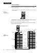
RTD RTD Input Procedure Equipment Required • 1K precision decade box with 0.01 resolution Setup and Calibration 1. Connect the AC voltage L1, L2 and ground to the proper terminals on the Series 988. See Chapter 2 in the user's manual. 2. For Input #1 calibration: Connect the decade box to terminals #8, 9 and 10 on the 988 terminal strip, see below. Use 20 to 24 gauge copper wire.
mA Process Input mA Process Input Procedure 0 to 20mA and 4 to 20mA units Equipment Required • Precision current source, 0-20mA range with 0.01mA resolution Setup and Calibration 1. Connect the AC voltage L1, L2 and ground to the proper terminals on the Series 988. See Chapter 2 in the user's manual. 2. For Input #1 calibration: Connect the voltage source to terminal #8 (-) and terminal #10 (+) on the 988 terminal strip. Use 20 to 24 gauge copper wire.
VDC Process Input VDC Process Input Procedure 0 to 5VDC and 0 to 10VDC units Equipment Required • Precision Voltage source 0-10 volt minimum range with .001 volt resolution. Setup and Calibration 1. Connect the AC voltage L1, L2 and ground to the proper terminals on the Series 988. See chapter 2 in the user’s manual. 2. For Input #1 calibration: Connect the voltage source to terminal #9 (+) terminal #10 (-) on the 988 terminal strip. Use 20 to 24 gauge copper wire.
mVDC Process Input mVDC Process Input Procedure 0 to 50mVDC and 0 to 100mVDC units Equipment Required • Precision millivolt source, 0-100mV minimum range with 0.001mV resolution Setup and Calibration 1. Connect the AC voltage L1, L2 and ground to the proper terminals on the Series 988. See Chapter 2 in the user's manual. 2. For Input #1 calibration: Connect the millivolt source to terminal #8 (-) and terminal #10 (+) on the 988 terminal strip. Use 20 to 24 gauge copper wire.
Slidewire/Current Slidewire Feedback Input Procedure Equipment Required • 1K precision decade box with 0.01 resolution Setup and Calibration 1. Connect the AC voltage L1, L2 and ground to the proper terminals on the Series 988. See Chapter 2 in the user's manual. 2. Connect the decade box to terminal #18 and #20 on the 988 terminal strip. Place a jumper wire between terminal #19 and #20. Use 20 to 24 gauge copper wire. 3. Apply power to the unit and let it warm up for 15 minutes.
mA Process Output mA Process Output 1 & 2 Procedure Equipment Required • 4 1/2 digit digital multimeter Setup and Calibration 1. Connect the AC voltage L1, L2 and ground to the proper terminals on the Series 988. See Chapter 2 in the user's manual. 2. For Output #1 calibration: Connect the digital multimeter to terminal #12 (+) and terminal #14 (-). Set the DMM to read a range of 0 to 20mA. Connect the leads of the DMM to measure current.
VDC Process Output VDC Process Output 1 & 2 Calibration Equipment Required • 4 1/2 digit Digital Multimeter Setup and Calibration 1. Connect the AC voltage L1, L2 and ground to the proper terminals on the Series 988. See Chapter 2 in the user's manual. 2. For Output #1 calibration: Connect the digital voltmeter to terminal #13 (+) and terminal #14 (-). Set the DVM to read a range of 0 to 10VDC. Connect the leads of the DVM to measure volts DC.
Retransmit mA Retransmit Output 3 Procedure Equipment Required • 4 1/2 digit Digital Multimeter Setup and Calibration 1. Connect the AC voltage L1, L2 and ground to the proper terminals on the Series 988. See Chapter 2 in the user’s manual. 2. Connect the digital multimeter to terminal #1 (+) and terminal #2 (-). Set the DVM to read a range of 0 to 20mA. Connect the leads of the DVM to measure current. 3. Apply power to the unit and let it warm up for 15 minutes.
WATLOW Series 988 Calibration Manual
Watlow Process Controls Calibration Manual Watlow Controls, 1241 Bundy Blvd., P.O.