Silver Series EM Operator Interface Terminals Addendum to EZwarePlus Programming Manual Operator Interface Terminals 1241 Bundy Boulevard, Winona, Minnesota USA 55987 Phone: +1 (507) 454-5300, Fax: +1 (507) 452-4507 http://www.watlow.com 0600-0102-0000 Rev. A April 2014 ©2014 Watlow. All rights reserved.
TC Table of Contents Chapter 1: Introduction ..................................................................................3 Additional Resources .................................................................................3 Chapter 2: Install and Wiring .........................................................................4 Connecting via Modbus RTU (232/485) .....................................................4 Connecting via Modbus TCP (Ethernet)..............................................
1 Chapter 1: Introduction The Silver Series EM Operator Interface Terminals (OITs) are powerful human machine interfaces for equipment and processes. EZwarePlus is easy-to-use and flexible software for creating the windows, buttons, displays, gauges and other screen items with which operators interact on the OIT. The purpose of this addendum is to quickly get you up and running with the OIT and software when used with Watlow controllers.
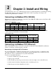
2 Chapter 2: Install and Wiring Consult the Watlow Silver Series EM Installation Guide for detailed information on installing and wiring the OITs. This chapter provides important additional information regarding connecting to and communicating with Watlow controllers. Connecting via Modbus RTU (232/485) The tables below indicate to which pins on the Silver Series EM OIT’s DB9 connectors the Watlow EZZONE® screw terminals should connect.
• The IP address is listed in the System settings window on the Network tab. (If Auto Get IP Address is selected, the IP Address is not editable. If you want to configure the OIT for a fixed address, select IP address get from below, and enter the IP address here. • Click OK to close the System settings window on the OIT. Hints for using the Virtual Keyboard to enter the OIT password and IP addresses: • It can take a few seconds for the Systems settings dialog with the password field to appear.
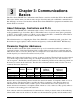
3 Chapter 3: Communications Basics The Silver Series EM OIT can communicate with Watlow controllers via Modbus TCP or Modbus RTU. This section defines terms you will encounter and provides information about Modbus communications that will help you create a user interface with the Silver Series EM OIT for equipment and machines that include Watlow controllers. About Gateways, Controllers and PLCs The Silver Series EM OIT can communicate with a variety of devices.
supply “the addresses.” So to use any two products together you need to know whether or not you have to convert the specified “address” in order to get the result you want. EZwarePlus’s Modbus drivers call the data block, “Device type” and for “Address” expect the memory location’s absolute address without the data block number. For example, to access a value in a holding register with absolute address 401,905, for Device type you select the data block “4x” and enter “1905” in the Address field.
For example, the EZ-ZONE PM Integrated Controller Models User’s Manual lists Map1 and Map 2 addresses for Process Value for Analog Inputs 1 and 2. If the Data Map parameter is set to Map 1 then the Process Value for Analog Input 2 is read at address 441 (the listed address plus one), but if Data Map is set to Map 2 then the Process Value for Analog Input 2 is read at address 451. The address for the Process Value for Analog Input 1 is the same for Map 1 and Map 2.
ZONE controllers via Ethernet, add three Modbus TCP/IP Master devices to the device list in the System Parameter Settings dialog each configured to communicate with one controller. Addressing Parameters in Multiple Controllers Normally the Silver Series EM OIT assumes that any register address you enter when communicating via Modbus RTU is associated with the controller at the network address you set in the PLC default station no field in the Device Properties under the System Parameter Settings.
In such a system the Silver Series EM OIT is connected to and configured to communicate with the gateway. The gateway presents itself as a single device on the Modbus network; the OIT does not communicate with the controllers, only with the gateway. The gateway is configured by the user with an address offset for each controller connected to it. That address offset is added to the parameter addresses for the controller.
4 Chapter 4: Programming Tutorials The following sections guide you through creating a first project using EZwarePlus and a Silver Series EM OIT that communicates with a Watlow controller. Create a First Project The following procedure guides you through the process of configuring a Silver Series EM OIT to communicate with a Watlow Controller. 1) To launch EZwarePlus: on the Windows task bar click Start, click All Programs, click Watlow, click EZwarePlus and click EZwarePlus.
6) In the System Parameter Settings dialog, under the Device List, click New… (002) 7) For PLC type, choose the appropriate driver. See the table below. 8) For PLC I/F, choose the appropriate hardware interface. See the table below. 9) For PLC default station no. type the controller’s address. Typically this is 1 for the first controller.
For part numbers like… with… For PLC type choose… For PLC I/F choose… PMxxxxx-2xxxxxx EZKx-2xxx-xxxx RMAx-x2xx-xxxx Modbus RTU Modbus RTU Master RS-232 or RS-485 2W* PMxxxxx-3xxxxxx EZKx-3xxx-xxxx Modbus TCP Modbus TCP/IP Master Ethernet RMAx-x3xx-xxxx Other Watlow Controllers Modbus RTU Modbus RTU Master RS-232 or RS-485 2W* *Both 232 and 485 are available; choose the one to which you have connected the OIT.
) To set up communications with controllers connected to other COM ports or to configure additional controllers communicating via Ethernet: • Click New... • Repeat from step 7 above. 15) Click OK to close the System Parameter Settings dialog. 16) Save the project: • From the File menu, choose Save. • In File name type First Project.emtp. • Click Save.
4) Ensure the Name is Window_011 and the Window no. is 11. 5) Set Width to 420. 6) Set Height to 300 (272 for the 4.3 in. OIT). 7) To set the background color to white: • In the Background group, next to Color click . • Select the white color swatch. • Click OK. (008) 8) In the Popup window group, set Start pos. X to 120 (0 for the 4.3 in. OIT). 9) In the Popup window group, set Start pos. Y to 120 (0 for the 4.3 in. OIT). 10) Click OK. 11) In the Open Window dialog, select Window_11. 12) Click Open.
5) For PLC name choose the Modbus Master or Modbus TCP/IP Master. 6) For Device type choose 4x. (075) 7) For Address enter the address of the heat power for your controller. See the table. 8) Select the data type in the field below the Address field. See the table.
10) Click the Outline tab. 11) In Degree set Start degree to 270. 12) In Degree set End degree to 90. 13) In Background uncheck Full circle. 14) In Tick marks check Enable. 15) For Tick marks Color, select black. 16) In Tick marks set Main scale to 6. 17) In Tick marks set Sub scale to 1. 18) In Tick marks set Length to 6. (010) 19) Click the Limits tab. 20) Set Value Zero to 0. 21) Set Value Span to 100. 22) Check Range limits Enable. 23) Set Width to 3. (011) 24) Click OK.
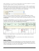
27) Double-click the meter to open the Meter Display Object’s Properties dialog. 28) Click the Profile tab. 29) Set X to 140. 30) Set Y to 60. (012) 31) Set Width to 140. 32) Set Width (%) to 100. 33) Click OK. 34) From the File menu choose Save. Add a Numeric Display This example assumes you have created a window in a project that is configured to communicate with a Watlow Controller and that window is open in EZwarePlus. 1) On the Objects menu, click Numeric/ASCII then choose Numeric Display.
6) On the Numeric Format tab. 7) In Data format set the data type. See the table. 8) On the Font tab set Align to Right. 9) Click OK. (013b) For this This Enter this Choose this controller… parameter… Address*… Data Type… RMCxxxx-xxxxxxx 2513 32-bit Float Closed Loop RMHx-xxxx-x1xx 5233 32-bit Float Working/Active PMxxxxx-xxxxxxx 2173 32-bit Float Set Point STxx-xxMx-xxxx 204 32-bit Float (Read Only) ST via RUI Gateway 2173 32-bit Float Other Controllers Consult the controller manual.
Add Increment and Decrement Buttons This example assumes you have created a window in a project that is configured to communicate with a Watlow Controller and that window is open in EZwarePlus. To add a button that increments the set point: 1) On the Objects menu, click Button then choose Set Word. 2) Click the General tab. 3) In Description type Increment Set Point. 4) For PLC name choose Modbus RTU Master or Modbus TCP/IP Master. 5) Click Setting… 6) For Device type choose 4x.
16) Click Shape Library… 17) Click the new library icon Select Lib… 18) In the EZwarePlus program’s library directory (typically: C:\Watlow\EZPlus\libr ary) select Arrows 1.plb. (016a) 19) Click Open. 20) Locate the button with the triangular arrow pointing up and click it. 21) Click OK to close the Shape Library. 22) Click OK to close the New Set Word Object dialog. (016) 23) Click to place the button. 24) Use the handles to adjust the size of the button.
To add a button that decrements the set point: 1) Click the increment button to select it. 2) From the Edit menu, choose Copy. 3) From the Edit menu, choose Paste. 4) Drag the new button to an appropriate position. 5) Double click the new button to edit its properties. (018) 6) On the General tab change: • Description to Decrement Set Point • Set Style to Press and hold decrement (JOG--). 7) Set Bottom Limit to 0.
Add an Option List for Control Mode This example assumes you have created a window in a project that communicates with a Watlow Controller and that window is open in EZwarePlus. 1) On the Objects menu, click Button then choose Option List. 2) Click the General tab. 3) In Comment type Control Mode. 4) Set Mode to Dropdown list. 5) Set Item No. to 3. 6) In the Monitor address group: • For PLC name choose Modbus RTU Master or Modbus TCP/IP Master. • Click Setting… • For Device type choose 4x.
8) In the Values column type the numeric and in the Item data the text that corresponds to each option you want to include. See the table. 9) Click OK to close the New Option List Object dialog. (020) Item 0 1 2 3 (error) Value 10 54 62 Enumerated Value Auto Manual Off 10) Position the cursor near the bottom center of the window layout and click to place the multi-state switch. (You may have to move the other objects around to fit everything.) 11) From the File menu choose Save.
Add a Button to Close the Popup Window This example assumes you have created a window in a project that communicates with a Watlow Controller and that window is open in EZwarePlus. 1) On the Objects menu, click Button then choose Function Key. 2) On the General tab, in Comment type Close Window. 3) Select Close window. 4) On the Shape tab, uncheck Use shape. (023) 5) Check Use picture. 6) Click Picture Library… 7) Click the new library icon 8) Select Computer.flb. 9) Click Open.
16) Click the Profile tab 17) Set Position X to 375. 18) Set Position Y to 5. 19) Set Size Width to 40. 20) Set Size Height to 40. 21) Click OK. 22) From the File menu choose Save. (025) Edit the Startup Window This example assumes you have created a popup window open in EZwarePlus in a project that is configured to communicate with a Watlow Controller. To add text to the start up window: 1) From the Window menu, choose 1 10 – WINDOW_010. 2) From the Draw menu choose Text.
6) Position the cursor centered in the top third of the window layout and click to place the text. 7) From the File menu choose Save. Add a Numeric Display to the main window: 1) On the Objects menu, click Numeric/ASCII and choose Numeric Display. 2) Click the General tab. 3) In Description type Process Variable. 4) For PLC name choose Modbus RTU Master or Modbus TCP/IP Master. 5) For Address choose 4x.and enter the address of the Analog Input 1 Process Value. See the table.
11) Move the cursor with the outline to position the display field in the center of the screen and click to place it. 12) From the File menu choose Save. (030) To create a function key on Window10: 1) On the Objects menu, click Button then choose Function Key. 2) On the General tab, in Comment type Loop 1 Settings. 3) Select Display popup window. 4) For Style choose No title bar. (031) 5) For Window no. select 11. Window_011. 6) Click the Shape tab. 7) Check Use shape.
18) Click OK. 19) Position the cursor and click to place the function key. 20) From the File menu choose Save. (032) Compile and Download the Project This example assumes you have a project that is ready to compile and load into an OIT. To compile the project: 1) From the Tools menu, choose Compile. 2) Click Compile. 3) After the project is compiled, click Close.
To download via Ethernet: 1) Determine the OIT’s IP address: • If you don’t already know the OIT’s IP address, follow the instructions in Determining or Setting the OIT’s IP Address on page 4, note the IP address for use below. 2) In EZwarePlus from the Tools menu, choose Download. 3) HMI IP select or enter the OITs IP address. 4) Set Password to the OITs password (111111 by default). 5) Check Firmware, if not already checked. 6) Check Reboot HMI after download, if not already checked. 7) Click Download.
To download the project via a USB drive to an OIT: 1) Connect at USB drive to the PC 2) From the Tools menu choose Build Data for USB Disk or SD Card Download… 3) Click Browse… (038) 4) Locate and select the USB drive. Note: Do not select a sub directory of the USB drive. Select the root. 5) Click OK to close the Browse For Folder dialog. (039) 6) Click Build. 7) When the files are transferred successfully, click OK. 8) Click Exit to close the USB Disk/CF Card/SD Card Data dialog.
3) With the Virtual Keyboard enter the Password. (By default this is 111111.) Note: If you have difficulty entering the password, see the hints below. 4) On the Download Settings dialog make sure Download Project Files is checked. 5) Click OK. 6) In the Pick a Directory dialog expand the usbdisk folder by clicking the plus (+) next to it. 7) Select the disk_a_1 folder. Note: The OIT represents the USB drive with a folder icon and a name it assigns such as disk_a_1.
• In Comment type a description of the data to be copied such as “PV 1”. • For Address type choose Word. • For Interval choose a value that is the same as or less than the amount of time you want between data samples. • In No. of words type word size of the parameter’s data type. See table. • For Source address PLC name choose Modbus RTU Master or Modbus TCP/IP Master. • For Source address device type choose 4x. • In Source address Address type the address of the parameter to be logged.
3) Click Exit to close the Data Transfer (Timebased) Object window. (043) To set up data sampling to log the data: 1) On the Objects menu, click Data Logging then choose Data Sampling. 2) Click New… (044) 3) In Comment type a description for the set of data such as “Loop 1”. 4) For Sampling mode choose Time-based. 5) For Sampling time interval choose the time between samples. 6) For Read address PLC name choose the OIT (“Local HMI” by default). 7) For Read address device type choose LW.
8) In Read address Address type the first address to which data was copied. In the example, this is 200. 9) In Max. data records type the number of records to save in a file. 10) Click Data Format… 11) For each item to be logged in the file: • Click New… (046) • For Data type choose the data type of the item being logged. Typically 32-bit Float). • In Comment Enter a description for the item to be logged, for example “PV 1”. (047) • Click OK. 12) Click Exit to close the Data Format window.
15) Click OK to close the Data Sampling Object set up window. 16) Click Exit to close the Data Sampling Object window.
Create a Graph This example assumes you have a project with at least one controller and that you have previously configured a time-based data sampling object. To create and open a window to use for the trend. 1) From the Window menu, choose Open Window. 2) Click New… (056) 3) Click Base Window. (007) 4) In Name type Trend. 5) Click OK. 6) In the Window list select Trend. 7) Click Open. (057) To create buttons to open the Trend window and return to the first window: 1) Select window 10.
7) Edit the Comment to read Trend Graph Window. 8) Choose Change fullscreen window. 9) For Window no. choose 12. Trend. (066) 10) Click the Label tab. 11) Edit the Content to read Trend. 12) Click OK to close the Function Key Object’s Properties window. 13) If necessary, select the function key by clicking it. 14) From the Edit menu, choose Copy. 15) Select window 12 Trend. 16) From the Edit menu, choose Paste. 17) Position the button centered at the bottom of the screen.
4) For Trend type choose Real-time. 5) For Distance between data samples/X axis time range choose Time. 6) In Distance type the number of seconds the width of the trend graph will represent. For example, if you want to see two minutes of data at once, type 120. 7) Click the Trend tab. 8) Choose a Frame color and a Background color. (052) 9) Click the Channel tab. 10) For each channel to be graphed: • In the Data sampling object group check Display.
12) Place and size the trend object. (053) 13) Optional: In the Trend Display Object Properties dialog Trend tab enable the Grid and set it up to display the time. (054) 14) Optional: Use the Scale tool to add a scale and labels with the Text tool. Color coordinate these or add a legend if the trend channels don’t all have the same zero and span.
Use Recipes This example assumes you have a project with at least one controller in which the recipe memory has not already been used for something else. In this example we will create a recipe that has five parameters from one controller. For each parameter we will create a data transfer object that saves the parameter’s value in the recipe in the OIT.
1) From the Objects menu choose Data Transfer (Triggerbased). 2) In Comment type “Recipe Save:” and the name of the name of the parameter (such as “Loop 1 Set Point”. 3) For Source address PLC name choose Modbus RTU Master or Modbus TCP/IP Master. 4) For Source address choose 4x and enter the address of the parameter. 5) In No. of words type word size of the parameter’s data type. See Table. 6) Click Setting… 7) For Destination address PLC name choose the OIT (Local HMI by default).
11) Click OK to close the Address dialog 12) For Mode choose External Trigger. 13) For Trigger address PLC name choose the OIT (Local HMI by default). 14) For Trigger address Device type choose LB to use an internal bit to cause the OIT to store values in a recipe. 15) In Trigger address Address type 500. 16) Click the Label tab. 17) Check Use label. 18) Set State to 0. 19) In Content type the name of the parameter. 20) Click OK. 21) Place the Data Transfer (Trigger-based) object on the screen.
1) From the Objects menu choose Data Transfer (Triggerbased). 2) In Description type “Recipe Load:” and the name of the parameter (such as “Loop 1 Set Point”). 3) For Source address PLC name choose the OIT. 4) For Source address choose RW and type the recipe address for the item. (062) 5) If you set up the recipe save to use and index register: • Click Source address Settings… • Check Source address Index register • For Source address Index choose INDEX 0 (16-bit). • Click OK to close the Address dialog.
To create a button to trigger the data transfer objects to copy the values currently in the controller to the corresponding recipe memory in the OIT: 1) On the Objects menu, point to Button and choose Set Bit. 2) In Description type “Save Recipe”. 3) For PLC name choose the OIT (Local HMI by default). (063) 4) For Address choose LB and type 500. 5) For Set style Choose Momentary. 6) Click the Label tab. 7) Check Use label. 8) In Content for state 0 type “Save to OIT”. 9) Click OK. 10) Place the button.
Optional: To see what you are copying from the controller to the OIT’s recipe memory, create an object displaying the current value in the controller next to each Data Transfer (Trigger-based) object. Create a label that indicates what the fields are such as “Current Controller Values”. Optional: To see or edit directly what is saved in recipe memory create a data entry object for each recipe item. These objects should display the values of the data in the RW memory at the recipe addresses.
Address indexing allows a screen object to display and set the value of different memory locations depending on the value in the index. In this example we use LW-9200 as the address index. Whatever value the index is set to is added to the address in the data transfer (and recipe display) objects. When the index value is zero, the first recipe is used. When the index is 10 the second recipe is used. When the index is 20 the third recipe is used.
To select the recipe to save to or load from create a multi-state switch to select the recipe as follows: 1) On the Objects menu point to Buttons and choose MultiState Switch. 2) In Description type “Recipe Selector”. 3) Click Read address Setting… 4) For PLC name choose the OIT (Local HMI by default). 5) Check System tag. 6) For Device type choose LW-9200 (16bit) : address index 0. 7) Click OK to close the Address dialog.
17) Click Setting… 18) For each state enter the appropriate offset Value. For state 0 enter 0. For state 1 enter a value that will offset the beginning of the second recipe beyond the end of the first in the recipe memory. 19) Click OK to close the Mapping window. (070) Note: The first recipe is selected with the multi-state switch in its state 0.
Silver Series EM OIT 50 Watlow Addendum