ANAFAZE 12LS Installation And Operation Manual Revision 3 August 1, 1991 Copyright (c) 1990 Watlow Anafaze, Incorporated 334 Westridge Dr Watsonville, CA 95076 Phone: 831-724-3800 Facsimile: 831-724-0320 All RIGHTS RESERVED: No part of this publication may be reproduced, stored in a retrieval system or transmitted in any form by any means; electronic, mechanical, photo copying, recording, or otherwise, without the prior written permission of ANAFAZE, Inc. Printed in U.S.A.
STATEMENT OF WARRANTY ANAFAZE, Incorporated warrants that the Products furnished under this Agreement will be free from material defects in material and workmanship for a period of one year from the date of shipment. The customer shall provide notice to ANAFAZE, Incorporated of any defect within one week after the Customer's discovery of such defect.
WARNING ANAFAZE HAS MADE EFFORTS TO ENSURE THE RELIABILITY AND SAFETY OF THE 12LS AND PROVIDE RECOMMENDATIONS FOR ITS SAFE USE IN SYSTEMS APPLICATIONS. PLEASE NOTE THAT IN ANY APPLICATION, FAILURES CAN OCCUR THAT WILL RESULT IN FULL CONTROL OUTPUTS OR OTHER OUTPUTS THAT MAY CAUSE DAMAGE OR UNSAFE CONDITIONS IN THE EQUIPMENT OR PROCESS CONNECTED TO THE ANAFAZE 12LS.
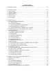
ANAFAZE 12LS TABLE OF CONTENTS 1.0 INTRODUCTION..................................................................................................................1-1 2.0 SPECIFICATIONS ................................................................................................................2-1 2.1 Analog Inputs......................................................................................................................2-1 2.2 Control Capability...................................................
4.4 OPERATIONAL MENUS..................................................................................................4-9 4.4.1 CHANGE SETPOINT..................................................................................................4-9 4.4.2 SET LOOP TO MANUAL/AUTO.............................................................................4-10 4.4.3 ADJUSTING OUTPUT LEVELS MANUALLY ......................................................4-10 4.5 SETUP MENUS .........................................
.0 SOFTWARE ..........................................................................................................................6-1 6.1 ANASOFT .........................................................................................................................6-1 6.2 CUSTOM APPLICATION PROGRAMS.........................................................................6-1 7.0 TROUBLE SHOOTING INFORMATION ...........................................................................7-1 7.
vii
1.0 INTRODUCTION The ANAFAZE 12LS is a powerful 1/8th DIN controller that delivers 12 fully independent loops of PID control. It functions as both a stand alone controller and as the key element in computer supervised data acquisition and control systems. An LCD front panel display and a touch keypad are available for local entry of control and other operating parameters. The ANAFAZE 12LS can also be supervised by a computer or programmable controller through the standard serial interface.
The ANAFAZE 12LS front panel provides an intelligent method for both viewing the process conditions and operating the controller. Displays show information in increasing detail: bar graph summary, single loop displays, and detailed guided setup menus. For operating security, all front panel entries can be password protected with two levels. With the panel "unlocked" common operator changes, such as setpoint or manual/auto, are made easier with single dedicated keys.
Guided Menus Simplify Setup The ANAFAZE 12LS directs operator and supervisor changes with guided menus. Two levels are provided: one for operator changes and one for supervisor controller setup. Operator Changes: Single dedicated keys are used to make process changes from the single loop display. The setpoint can be changed, the loop can be set to auto or manual, and ramp and soak loops can be started, held, or stopped. If the loop is set to manual, the percent output can be changed.
Digital Inputs and Outputs Expand Versatility Digital inputs and outputs are provided to further enhance the ANAFAZE 12LS flexibility. Digital outputs are provided for global alarms, systems status, individual high and low alarms, and ramp and soak events. Digital inputs are available to control the ANAFAZE 12LS in response to external conditions. Annunciator Alarm Output: One of the digital outputs is setup as a global output for connection to an annunciator. This output is turned on when any alarm occurs.
2.0 SPECIFICATIONS 2.1 Analog Inputs Analog Inputs 12, Solid state, common ground. Isolation: Between inputs and ground: 10volts peak. A/D Converter: Integrating voltage to frequency. Range: -10 to 60mv, can be changed with scaling resistors to any range from 0 up to 25v. Resolution: 0.02%, greater than 12 bits. Accuracy: 0.1% at 25°C Calibration: Automatic zero and full scale. Temperature Coef: Less than 100ppm/°C, 0.01%/°C. Normal Mode Rejection: 60db at 60Hz, full scale range maximum.
2.2 Control Capability Number of Loops: 12, Dual Output. Control Outputs: Cycle Time Proportioning, Distributed Zero Crossing, or On/Off; all independently selectable for each loop. Control Action: Reverse [heat] or Direct [cool], independently selectable for each loop. Digital Control Outputs: Nominal 5vdc at 10ma to driveoptically- isolated solid-state relays. Cycle Time: Programmable foreach loop, 1-255 secs. Output Resolution: 16 bits. 2.
Power input: 10 to 30VDC, 3 Watts typical, 110VAC adapter provided.
3.0 INSTALLATION There are some precautions that must be observed when installing ANAFAZE 12LS. WARNING! -- ELECTRICAL SHOCK DANGER It is very important that all system power including the power input be disconnected before servicing the ANAFAZE 12LS. HIGH VOLTAGE MAY BE PRESENT EVEN WHEN POWER IS TURNED OFF! To reduce the danger of electrical shock always mount the 12LS in an enclosure that prevents personal contact.
3.1.1 MOUNTING For optimum performance when directly connecting thermocouple inputs the unit should be protected from thermal shocks whenever possible. This will minimize any temperature gradients across the terminal strips and ensure the highest accuracy. The required panel cutout is a rectangular hole 46mm x 92mm [1.81in x 3.63in]. This should be carefully cut since the 1/8th DIN specification only allows a front panel of 48mm x 96mm [3.78in x 3.78in] -- so there is not a lot of room for error.
1/8th DIN HOUSING 3-3
3.1.2 EXTERNAL WIRING During wiring, it is recommended that the 12LS electronics be removed or temporary covers be put over the housing slots to ensure pieces of wire do not enter the housing and lodge in the electronics. Always ensure that the housing is clean when the electronics is plugged in. The successful installation of the ANAFAZE 12LS control system will be the result of selecting the proper equipment and the use of correct installation techniques with appropriate material.
4. Use Thermocouple Extension Wire for all thermocouple (T/C) inputs. Most T/C Ext. Wire is solid wire unshielded. When using such, the shield function cannot be utilized and only 16, 18, or 20 ga should be used. Install all T/C wiring in its own conduit away from AC Power and High Power wiring. Depending on type and wire size up to 400-500 feet in length may be used to be within stated accuracy and source impedance. 5. Use multiconductor stranded shielded cable for analog inputs.
3.1.4 RECOMMENDED CABLES P/N Use these cables or equivalent. |--------------------------------------------------------------| ¦ FUNCTION ¦ MFR P/N ¦ # of WIRE ¦ |--------------------------------------------------------------¦ ¦ Analog Inputs ¦ Belden #9154 ¦ 2-20ga ¦ ¦ ¦ Belden #8451 ¦ 2-22ga ¦ ¦ ¦ ¦ ¦ ¦ RTD Inputs ¦ Belden #8772 ¦ 3-20ga ¦ ¦ ¦ Belden #9770 ¦ 3-22ga ¦ ¦ ¦ ¦ ¦ ¦ T/C Inputs ¦ T/C EXT.
3. Separate the 120 vac power leads from the low level input and outputs leads from the ANAFAZE. Do not run the digital outputs or PID control outputs leads in the same wire bundle as any 120 vac wires. Inputs leads should never be run in the same bundle with any high power leads. See 3.3.3. 4. If, E-M relays are required and must be in the same panel as the ANAFAZE equipment, use a .
3.2 TERMINAL BLOCK AND CONNECTOR LAYOUT The ANAFAZE 12LS terminal blocks and connectors are assigned according to the following two pages. Subsequent sections provide detailed connection descriptions. 12LS REAR PANEL NOTES: 1. THE CH (LOOP NUMBER) +IN IS THE ANALOG POSITIVE OF THE INPUT SIGNAL FOR THAT LOOP. 2. -IN COM IS THE ANALOG COMMON NEGATIVE OF THE INPUT SIGNAL. 3. CTRL COM IS THE COMMON FOR THE DIGITAL I/O CIRCUITS, SERIAL COMMUNICATIONS, AND IS CONNECTED TO THE NEGATIVE OF THE POWER SUPPLY. 4.
REMOTE TERMINAL BLOCK CONNECTIONS The remote terminal block (RTB) provides the control outputs and additional digital inputs and outputs as follows: |------------------------------------------------------------| ¦ FUNCTION ¦ TERMINAL ¦ FUNCTION ¦ |------------------------------------------------------------¦ ¦ +5VDC ¦ 1 ¦ 2 ¦ +5VDC ¦ ¦ CTRL COM ¦ 3 ¦ 4 ¦ CTRL COM ¦ ¦SPARE ¦ 5 ¦ 6 ¦ SPARE ¦ ¦SPARE ¦ 7 ¦ 8 | BOX SELECTED ¦ ¦ PIDHEAT 1 ¦ 9 ¦ 10 ¦ GLOBAL ALARM ¦ ¦ PIDHEAT 2 ¦ 11 ¦ 12 ¦ DIG OUTPUT 9 ¦ ¦ PIDHEAT
3.3 ANALOG INPUTS Connecting analog signals to the ANAFAZE 12LS is normally straightforward. Most thermocouples can be directly connected and mixed in any order. Other types of analog signals such as mAdc or Vdc require scaling resistors installed on the 12LS inputs. However, some problems may occur that could reduce accuracy and possibly damage the unit. Sections 3.1 through 3.4 indicate some of the potential areas for concern. [See typical input DIAGRAM in section 3.13]. 3.3.
3.3.5 INPUT SCALING The ANAFAZE 12LS contains an area that can be used to install resistors to scale input voltages and convert milliamp inputs to match the -10 to 60mv (-16.7% to 100%) input range. The input circuit is designed to enable connection of current inputs (such as 4 to 20ma), and voltage inputs. ANAFAZE will supply input scaling as needed -- order option 12LS-SI-XX.
3.3.6 VOLTAGE INPUTS DC Voltage inputs should be connected with the positive side to the CH +IN terminal and the negative side to one of the -IN COM terminal. The input range is -10 to +60 mv. Signals greater than 60 mv must be scaled with resistors to match the input full scale to 60 mv. The scaling resistor RA is selected as the voltage dropping and/or current limiting resistor. RB is selected for the 60 mv full scale dropping resistor.
WARNING Use of the grounded T/C, meaning that the T/C junction is at the same potential of the metal protection sheath of the T/C assembly, may cause calibration shifts and/or erratic temperature readings of the input. The use of a grounded T/C in a process using electrical energy for heating, may also cause damage to the 12LS.
If desired, a second input may be used to monitor the internal IRSM ambient temperature. Consult ANAFAZE for more information. 3.3.11 SCALING AND CALIBRATION The ANAFAZE 12LS includes a scaling provision to convert analog inputs into engineering units. Section 4.5.2.3 describes how to set the automatic scaling. 3.3.
3.4.1 PID CONTROL AND ALARM OUTPUTS CONNECTIONS Typical digital control outputs utilize external optically- isolated solid-state relays. These relays use a 3 to 32vdc input for control and can be sized to switch up to 100 amps at 480vac. For larger currents these relays can be used to drive contactors. |-----------------------------------------------------| ¦ NOTE: Control outputs are SINK OUTPUTS. They will be¦ ¦low when the output is ON. They should be connected ¦ ¦to the minus (-) side of SSRs.
3.5 COMPUTER SERIAL COMMUNICATIONS The ANAFAZE 12LS offers two types of serial communications: RS- 232 and RS-485. The RS-232 is used primarily for local communications of up to the recommended RS-232 distance of 50 feet. It can only be used with one ANAFAZE 12LS. More than one unit requires RS-485 The RS-485 is a voltage balanced, 4-wire, long distance, multi- point transmission interface. Up to 32 addresses can be set in the 12LS for one communication line.
3.5.3 RS-485 DESCRIPTION The EIA Standard RS-485 specifies only the electrical characteristics of generators (transmitters) and receivers for use in digital multi-point systems. The specification of transmission lines, signaling rates, protocols, etc. is left entirely up to the user. The transmitters and receivers selected by ANAFAZE also meet the requirements of RS-422. The following information is intended to make recommendations for the application of the RS-485 interface to ANAFAZE equipment.
3.5.3.2 RS-485 CONNECTIONS Connection of ANAFAZE controllers to a system computer requires an interface at the computer to convert RS-232 levels to RS-485. Anafaze recommends Black Box Model LD485A for this purpose. The LD485A should be configured for DCE operation, with the RTS/CTS delay jumper in the "on" position. ANAFAZE can supply this converter configured and checked out with the system on request. Normal Operation LD485A installation setup: 1. DCE operation (Dip shunt in XW1A socket) 2.
ANAFAZE 12LS connections for a single unit are as follows: Black Box LD485A 12LS TB 1 TXA ---------------------------------------- RX+ #25 ---|| ¦¦ 200 ΩTXB ---------------------------------------- RX- #23 ---|| RXA ---------------------------------------- TX+ #26 RXB ---------------------------------------- TX- #24 Shield ----- Earth Ground ------- Shield Do not Ground |-----------------------------------------------------| ¦ NOTE: Connect the shields to EARTH ground only at ¦ ¦the computer or other 48
4.0 FRONT PANEL OPERATION AND DISPLAYS The 12LS front panel provides the operator interface for the controller. The 12LS may be fully programmed and operated by using the eight keys on the front panel. The 32 character display shows process information and setup displays. The 12LS will power up with the BAR GRAPH display being shown. Press the BACK key to get to the SINGLE LOOP display. Refer to section 4.2 for more detailed information on these and other system displays.
|- - - - - - - - - - - - - -| Back ¦ ¦ ¦ |--------------| ¦ | - -¦ SETUP || ¦ ¦ RAMP AND SOAK¦ ¦ ¦ |--------------|¦ ¦ ¦ ¦ ¦ |-Profile # ¦ ¦ |-Copy Prof. ¦ ¦ |-Tol.
4.1 FRONT PANEL KEYS The four main function keys on the front panel are used to perform specific operations : |-----| ¦CHNG ¦ ¦ SP ¦ |-----| o Adjust the setpoint on displayed loop. |-----| ¦ MAN ¦ ¦AUTO ¦ |-----| o Toggle loop status between MANUAL and AUTO. o Adjust output power level of loops in MANUAL mode. |-----| ¦RAMP ¦ ¦SOAK ¦ |-----| o No function if OPTION not installed. o Assign a ramp/soak profile to selected loop. o Perform operations on profile already assigned.
4.2 DISPLAYS On power-up the controller defaults to the BAR GRAPH display which shows the status of all 12 loops. From there the user may switch to the SINGLE LOOP display which provides more detailed information about any selected channel. The channel displayed in the SINGLE LOOP display may be changed by using the UP and DOWN ARROW keys.
4.2.2 SINGLE LOOP DISPLAY The SINGLE LOOP Display shows the detailed information for one loop at a time. The UP/DOWN arrows select the loop number. Press the BACK key to return to the BAR GRAPH display. FIGURE 4-3 identifies the data shown on the SINGLE LOOP Display.
|--------------------------------------------------------------| ¦ Table 4-1. LOOP STATUS DEFINITIONS ¦ |--------------------------------------------------------------¦ ¦ Loop Status Symbol ¦ ¦ |---------------------¦ Description ¦ ¦Bar Graph¦Single Loop¦ ¦ ¦ Display ¦ Display ¦ ¦ |---------¦-----------¦----------------------------------------¦ ¦ A ¦ AUTO ¦ Single output loop is in automatic ¦ ¦ ¦ ¦ control mode. The output power percent-¦ ¦ ¦ ¦ age displayed is for the heat output.
4.2.4 ALARM DISPLAY The ALARM display interrupts any system display. If more than one alarm is present the first alarm is shown.
4.3 GENERAL PROGRAMMING AND EDITING In general, the 12LS menu structure consists of several main menus each having a group of sub-menus beneath them. The user selects a main heading and then steps through the sub-menus until the desired menu is reached. Most menus will appear with a prompt denoting the parameter to be edited followed by a blinking question mark (?) and the current value or setting of the parameter.
4.4 OPERATIONAL MENUS All changes must start from the SINGLE LOOP display. The following changes can be made by pressing the associated front panel key: |----| ¦CHNG¦ o Adjust the setpoint on displayed loop. ¦ SP ¦ |----| |----| ¦ MAN¦ o Change loop status from Manual to Auto ¦AUTO¦ or vice-versa. |----| |----| ¦RAMP¦ o If option is installed, this key is used ¦SOAK¦ to change status of a Ramp/Soak profile.
4.4.2 SET LOOP TO MANUAL/AUTO To toggle the current mode from MANUAL to AUTO or from AUTO to MANUAL, press this key : |----| ¦MAN ¦ ¦AUTO¦ |----| Depending on the current loop status the display will appear as in one of the two following examples. The 5 represents channel 5. |----------------| ¦05 STATUS = MAN ¦ ¦ SET ? AUTO¦ |----------------| Loop in MANUAL mode. |----------------| ¦05 STATUS = AUTO¦ ¦ SET ? MAN ¦ |----------------| Loop in AUTO mode.
4.5 SETUP MENUS To change any other of the controller settings select the loop desired and from the SINGLE LOOP display enter the password key sequence by pressing these three keys in this order : |-----| |-----| |-----| ¦ENTER¦ ¦ALARM¦ ¦CHNG ¦ ¦ ¦-->¦ ACK ¦-->¦ SP ¦ |-----| |-----| |-----| In this way, the operational menus can be made available to operators while supervisors and other approved personnel familiar with the password sequence can access the setup menus.
LOOP SETUP DATA |--------------------------------------------------------------| ¦Date _________ ¦ ¦ ¦ ¦Controller Number _________ Loop Number ________ ¦ |--------------------------------------------------------------¦ ¦Setpoint _______ Manual/Auto Manual Output 1, HT ______ ¦ ¦ ¦ ¦Spread _______ Manual Output 2, CL ______ ¦ |--------------------------------------------------------------| |--------------------------------------------------------------| ¦ Input Settings ¦ ¦ ¦ ¦ Input Type ______ High PV ___
|-----------------------------------------------------| ¦ NOTE: Unless otherwise specified, in all examples ¦ ¦of menu displays in the following discussions about ¦ ¦editing and programming, the question mark (?) would ¦ ¦ be blinking and the multiple x's used represent the ¦ ¦ data or choice to be edited. When a menu is selected¦ ¦ the x's would show the current data setting and the ¦ ¦ question mark (?) would become an equal sign (=) ¦ |-----------------------------------------------------| 4.5.
The menu appears as: |----------------| ¦SAVE CURRENT ¦ ¦SETUP TO JOB ? x¦ |----------------| When this menu is first displayed the job number will be the number of the last job file selected, or 1 by default. Press YES to select the menu or NO to advance to the next menu. Press UP and DOWN to select the job number. Press ENTER to store current setup to the selected job file or press BACK to return to the SETUP GLOBAL PARAMETERS main menu heading. 4.5.1.
Press ENTER to store the new alarm delay setting or press BACK to return to the SETUP GLOBAL PARAMETERS main menu heading. 4.5.1.4 SETTING THE GLOBAL TIME BASE This menu allows setting of the global ramp and soak time base to units of hours and minutes or minutes and seconds. All time entries in ramp and soak profiles will assume the units of this setting. The default is hours and minutes.
4.5.1.6 POWER UP OUTPUT STATUS This menu is used to configure the initial power-up state of the control outputs. The controller will either initialize the outputs to OFF or to the last output state as it was left stored in memory. If OFF is chosen all control outputs are initially set to MANUAL mode at 0% output level. If MEMORY is chosen the outputs are restored to their condition when power was removed.
4.5.1.8 COMMUNICATION ERROR CHECKING METHOD This menu is used to select the checksum algorithm used in the ANAFAZE communications protocol. Either BCC (block check character) or CRC (cyclic redundancy check) may be chosen. |-----------------------------------------------------| ¦ NOTE: If using ANASOFT software to communicate to ¦ ¦the controller make sure that the ANASOFT INSTALL ¦ ¦program has been set for the same error checking ¦ ¦ method.
Press YES to select the menu or NO to advance to the next menu. Press UP and DOWN to toggle the selection between 9600 and 2400. Press ENTER to store the baud rate or press BACK to return to the SETUP GLOBAL PARAMETERS main menu prompt. 4.5.1.10 AC LINE FREQUENCY This menu is used to configure the controller to match the AC line frequency.
4.5.2 SETUP LOOP INPUT Press YES at this prompt to access menus to change parameters related to the channel input including : o Input type [thermocouple or other] o Engineering units to be displayed o Scaling 4.5.2.1 EDIT INPUT TYPE This menu allows configuration of the input sensor as either a thermocouple or a LINEAR input. Thermocouple types include J, K, T, S, R and B. Also available is a type called SKIP for unused channels.
The display appears as : |----------------| ¦LL INPUT ¦ ¦ UNITS ? xxx ¦ |----------------| Press YES to select the menu or NO to advance to the next menu. Press UP and DOWN to cycle through the available character choices. Press ENTER to store the character being edited. If the third character has just been entered the display will advance to the next menu. Otherwise, the display will move to the next character for editing and the steps are repeated.
The display for the high process variable will appear as : |----------------| ¦LL INPUT SCALING¦ ¦HIGH PV ? xxxx ¦ |----------------| Press YES to select the menu or NO to advance to the next menu. Press UP and DOWN to set the high process variable. Press ENTER to store the high process variable or BACK to return to the SETUP LOOP INPUT main menu prompt.
The low input reading is referenced to 60mV and is calculated using this equation: (see section 3.3.6) (Sensor Output @ Low PV) LOW RDG = (1000) * -----------------------( 60mV ) Press YES to select the menu or NO to advance to the next menu. Press UP and DOWN to set the low reading. Press ENTER to store the value or BACK to return to the SETUP LOOP INPUT main menu prompt. Linear Input Scaling Example: PROBLEM: We want to connect a pressure sensor to enable us to read pressure directly in PSI.
When the PV readout is reading below the true known PV level, add that amount to the High and Low PV scaling. When the PV readout is reading above the true known PV level, subtract that amount from the High and Low PV scaling. Example: A J T/C is reading 396 when true temperature is 400. Set the High PV to 1404 and the Low PV to -346. Example: A J T/C is reading 302 when true temperature is 300. Set the High PV to 1398 and the Low PV to -352.
4.5.3.1 PROPORTIONAL BAND The first selection for each output allows programming of the proportional band. The display bottom line appears as : |----------------| ¦ ¦ ¦ PB ? xxxx ¦ |----------------| Press YES to select the menu or NO to advance to the next menu. Press UP and DOWN to set the proportional band in engineering units. Press ENTER to store the value or BACK to return to the SETUP LOOP CONTROL PARAMS main menu prompt. 4.5.3.
4.5.3.4 OUTPUT FILTER This menu allows allows programming of the output filter. The output filter causes the controller to average multiple output calculations for smoother response. The bottom line of the display will appear as : |----------------| ¦ ¦ ¦ FILTER ? xx ¦ |----------------| Press YES to select the menu or NO to advance to the next menu. Press UP and DOWN to set the number of readings to average. Press ENTER to store the value or BACK to return to the SETUP LOOP CONTROL PARAMS main menu prompt.
|-----------------------------------------------------| ¦ NOTE: If the channel is operating as a single output¦ ¦loop (ref. 4.5.3) all prompts for the COOL output ¦ ¦data are suppressed. When the last HEAT output var- ¦ ¦ iable is programmed (OUTPUT LIMIT TIME) the display ¦ ¦ will return to the SETUP LOOP OUTPUTS? prompt. ¦ |-----------------------------------------------------| 4.5.4.1 OUTPUT TYPE The first menu for either heat or cool outputs is that which allows programming of the output type.
4.5.4.2 CYCLE TIME If Time Proportioning is selected as the output type the controller will prompt the user for a cycle time. The lower display will appear as : |----------------| ¦ ¦ ¦CYCLE TIME ? xxx¦ |----------------| Press YES to select the menu or NO to advance to the next menu. Press UP and DOWN to select desired cycle time(1 - 255 seconds). Press ENTER to store the cycle time or BACK to return to the SETUP LOOP OUTPUTS main menu prompt.
Press UP and DOWN to set the maximum output power percentage from 0 t 100%. Press ENTER to store the output limit or BACK to return to the SETUP LOOP OUTPUTS main menu prompt. Entering 100% as the limit effectively disables the limit function. 4.5.4.5 OUTPUT LIMIT TIME The length of time that a programmed output limit (ref. sec. 4.5.4.4) will be in effect is selectable from 1 to 999 seconds (1 second to over 16 minutes) or CONTINUOUS.
4.5.5.1 HIGH PROCESS ALARM SETPOINT This menu is used to set the point within the scaled sensor range at which the high process alarm is activated. The display appears as : |----------------| ¦LL HI PROC ALARM¦ ¦SETPOINT ? xxxx ¦ |----------------| Press YES to select the menu or NO to advance to the next menu. Press UP and DOWN to adjust the high process alarm setpoint. Press ENTER to store the setpoint or press BACK to return to the SETUP LOOP ALARMS main menu prompt. 4.5.5.
4.5.5.4 DEVIATION BAND ALARM This menu is used to set the deadband alarm value. The deviation alarm is a plus and minus alarm that is always relative to the setpoint. If the setpoint changes the actual alarm points also change. A separate digital output may be assigned to the high deviation alarm and the low deviation alarm. To edit the deviation alarm bandwidth the display will appear as: |----------------| ¦LL DEV.
Press ENTER to store the output assignment or press BACK to return to the SETUP LOOP ALARMS main menu prompt. 4.5.5.7 LOW DEVIATION ALARM OUTPUT ASSIGNMENT This menu is used to assign a digital output to be activated in the event of a low deviation alarm. Any of the 9 available digital outputs may be used or the output function may be turned OFF. The display appears as: |----------------| ¦LL LO DEV. ALARM¦ ¦OUTPUT NR ? xx ¦ |----------------| Press YES to select the menu or NO to advance to the next menu.
Press ENTER to store the status or press BACK to return to the SETUP LOOP ALARMS main menu prompt. 4.5.5.10 LOW PROCESS ALARM OUTPUT ASSIGNMENT This menu allows assignment of a digital output to be used by the low process alarm. Set to OFF to disable the output function or 1-9 for the desired digital output number. The display appears as: |----------------| ¦LL LO PROC ALARM¦ ¦OUTPUT NR ? xx ¦ |----------------| Press YES to select the menu or NO to advance to the next menu.
4.5.6.1 DIGITAL INPUT TESTING This is a view-only display showing the logic state of the 8 digital inputs as 1's (High) or 0's (Low). The display appears as: |----------------| ¦ DIGITAL INPUTS ¦ ¦ xxxxxxxx ¦ |----------------| Input 1 --| |-- Input 8 Press any key to advance to the TEST OUTPUT SELECTION display. 4.5.6.2 TEST OUTPUT SELECTION This menu allows the user to select one of the 9 digital outputs for manual operation.
4.6 RAMP AND SOAK OPTION The ramp and soak option turns the 12LS into a powerful batch controller. Along with the power comes a certain amount of complexity. In general, the features that are not as likely to be used have been set to default to a non-intrusive condition. For example, if there is not a requirement for digital inputs as triggers, they will be ignored by the profile.
4.6.1 DESCRIPTION A ramp / soak profile consists of several groups of parameters: those global to the profile as a unit, those defined as the "ready state" for the profile, and those specified for each segment of the profile. The "ready state" is assigned as segment 0, although it is not an executable segment. The remaining executable segments each comprise one time period within the profile in which either a change of setpoints occurs or a single setpoint is held.
+-------------------------------------------------------------+ ¦ PARAMETERS SPECIFIC TO EACH SEGMENT ¦ |-------------------------------------------------------------¦ ¦ Setpoint ¦ Specifies setpoint to be reached at the ¦ ¦ ¦ end of the segment. If the setpoint from¦ ¦ ¦ the previous segment is the same, this ¦ ¦ ¦ setpoint will be held during the segment¦ ¦ ¦ (soak).
This function may be enabled or disabled per segment via the tolerance parameter. If tolerance is OFF no guarantee of setpoint is made and the tolerance time is disregarded. If tolerance is any value between -99 and 99, other than 0 (OFF), then the total integrated input error time (time that the process variable is out of tolerance) is not allowed to exceed the specified alarm time for the segment.
4.6.3 PROFILE STATUS DISPLAY Whether in the TIME display, the CYCLE COUNT display or the PROFILE OPERATION menu, the upper line of the display will always show the current PROFILE STATUS. An example of this STATUS display line follows: Profile | Current Segment executing Assigned ¦ and total profile segments Loop ¦ ¦ Number | ¦ ¦ | First letter of current |----------------| loop status ¦05 A SEG01/07 R ¦ ¦ ¦ |----------------| Refer to TABLE 4-1 for description of the loop status symbols.
Use the UP and DOWN keys to change the profile letter. Profile assignment may be 'A' to 'L' for one of the twelve ramp and soak profiles stored in memory, or NONE for no profile. If, there is a profile assigned to the loop, the selection of a new profile requires stepping through the R/S display menu to get to the selection menu. Use the following steps: Step #1 Press the R/S key. The profile time display will be shown. Step #2 Press the R/S key. The profile cycle count display will be shown.
An example display follows: |----------------| ¦05 A SEG01/07 R ¦ ¦TIME LEFT= 34:28¦ |----------------| In this example loop 5 is running profile A. The loop is currently executing segment 1 of a total of 7 segments in the profile. The total time remaining in the profile is 34:28. This could be either 34 hours and 28 minutes or 34 minutes and 28 seconds. 4.6.6 CYCLE COUNT DISPLAY This display shows the profile status on the top line and the current cycle count on the bottom line.
|--------------------------------------------------------------| TABLE 4-2 Ramp / Soak Operations ¦ ¦ |--------------------------------------------------------------¦ ¦ Current ¦Available¦ Operation Description ¦ ¦ Status ¦ Mode ¦ ¦ |---------¦---------¦------------------------------------------¦ ¦ RUN ¦ HOLD ¦ Put loop into HOLD mode. All loop para- ¦ ¦ ¦ ¦ meters are "frozen" at current settings. ¦ ¦ ¦ ¦ ¦ ¦ HOLD ¦ CONT ¦ CONTinue from a hold condition.
|----------------------------------------------------| ¦ NOTE: When leaving ramp and soak mode the loop is ¦ ¦ placed in MANUAL mode and the output is set to 0. ¦ |----------------------------------------------------| Example problems and solutions PROBLEM: Length of a segment is unknown and depends solely on a trigger input for conclusion. SOLUTION: Enter the smallest interval possible, define a trigger for the subsequent segment.
PROFILE SETUP GUIDE 4-43
PROFILE SETUP GUIDE 4-44
|-----------------------------------------------------| ¦ NOTE: For RAMP AND SOAK option, if the loop is run- ¦ ¦ ning a ramp and soak profile, forcing it into manual¦ ¦ removesthe loop from ramp and soak mode. The user ¦ ¦ must reassign and restart the profile to return to ¦ ¦ automatic ramp and soak operation. ¦ |-----------------------------------------------------| 4.
UP/DOWN Select a profile designator [A-L].
ENTER BACK Open the selected profile for editing. The display advances to the Copy Profile Menu. Return to SETUP R/S PROFILE ? prompt. NO Select the default profile for editing. The display advances to Copy Another Profile. BACK Return to the SETUP R/S PROFILE ? prompt. 4.7.2 COPY ANOTHER PROFILE This menu allows copying of another profile into the profile currently selected. This shortcut method is useful when the majority of a profile is similar to one that already exists.
When any segment is out of tolerance for a period greater than the Tolerance Time entered, a tolerance alarm is generated. A tolerance alarm activates the global annunciator output and displays a 'T' in the alarm status position on the display. Display: |------------------| ¦ x OUT-OF-TOLRNCE ¦ ¦ ALARM TIME:?hh:mm¦ |------------------| x is the profile designator [A-L]. The ? flashes. hh:mm is the current out-of-tolerance time limit. YES Edit the tolerance limit time.
ENTER Store new ready state setpoint. Display will advance to Edit Ready Event States. BACK Return to SETUP R/S PROFILE? prompt. NO Skip edit. Leave ready setpoint as it is. Display will advance to Edit Ready Event States. BACK Return to the SETUP R/S PROFILE? prompt. 4.7.5 EDIT READY EVENT STATES This menu allows setting of default states for all possible 9 event outputs. These will be the output states whenever the loop is in the (S)TART state. The default for all outputs is OFF.
4.7.6 EDIT EXTERNAL RESET From this menu one of the eight digital inputs will be selected to provide an input for a external reset of this profile while in any of the R/S operational modes. A selection of 0 will disable this function. The same input may be assigned to more than one profile. |-----------------| Display: ¦ x EXTERNAL RESET¦ ¦ INPUT NUMBER? d ¦ |-----------------| The ? is flashing. x is the profile designator [A-L].
NO Select the default segment for editing. Display advances to Edit Segment Time. BACK Return to the SETUP R/S PROFILE? prompt. 4.7.8 EDIT SEGMENT TIME Use this menu to edit the segment time. Units are either Hours:Minutes or Minutes:Seconds depending on the global time base selected. |-----------------| ¦ x SEGMENT yy ¦ ¦ SEG TIME ?hhh:mm¦ |-----------------| Display: The ? flashes. x is the profile designator [A-L]. yy is the segment number [1-20].
YES Change current setpoint setting. Lower display SP =xxxx UP/DOWN Changes setpoint value. ENTER Stores new segment setpoint. Display advances to Edit Segment Events. BACK Returns to Edit Segment Number. NO Leave segment setpoint as it is. Display advances to Edit Segment Events. BACK Returns to Edit Segment Number. 4.7.10 EDIT SEGMENT EVENTS From this menu event outputs for the current segment may be defined. Each segment may have up to four event outputs defined.
YES Change the output assigned to this event. Lower display DOUT= xx UP/DOWN Select output number. [1-30, NO]. ENTER Assign output number to this event. Display advances to Edit Event State. BACK Return to Edit Segment Events. NO If an output is assigned to the current event the display advances to Edit Event State. If no output number is assigned the display advances to next event number. [1-4 and wraps around]. BACK Return to Edit Segment Events. 4.7.
4.7.13 EDIT SEGMENT TRIGGERS Use this menu to edit the trigger input assignments, their active states and their latching status for the current segment. Each segment may have two associated triggers. If a segment has any triggers defined at least one of them must be true before the segment will begin executing. Triggers may be latched or unlatched. The default assignment for all segment triggers is NO assignment. Latched triggers are checked only once at the beginning of a segment.
YES Edit input number assigned to this trigger. Lower display DIN = xx UP/DOWN Select input assignment. ENTER Assign input number to current trigger. If a pin number is assigned the display advances to Edit Trigger Active State. If NO is entered, the display advances to the next trigger. BACK number or delete Return to Edit Segment Triggers. NO Leave input assignment for this trigger as it is. If the trigger is assigned the display advances to Edit Trigger Active State.
4.7.16 EDIT TRIGGER LATCH STATUS Display: |--------------| ¦ a SEG TR DI¦ ¦ TRIG? UNLATCH¦ |--------------| The ? flashes. YES Change latch state of this trigger. Lower display UNLATCH UP/DOWN Select unlatch or latch status. ENTER Assign latch status for this trigger. Display advances to Edit Trigger Input Number for the next trigger. BACK Return to Edit Segment Triggers. NO Leave latch state assignment for this trigger as it is. Display advances to Edit Trigger Input Number for next trigger.
YES Change current tolerance value. Lower display TOL = xx UP/DOWN Set value [+99] ENTER BACK NO BACK Store new tolerance value. Display to Specify the Last Segment. advances Return to Edit Segment Number. Leave tolerance value as it is. Display advances to Specify the Last Segment. Return to Edit Segment Number. 4.7.18 SPECIFY THE LAST SEGMENT This menu is used to designate the final segment in the current profile by answering YES or NO to the question LAST?.
4.7.19 EDIT PROFILE CYCLES This menu is used to enter the desired cycles for this profile. Cycles is the number of times this profile is to be repeated without stopping. Cycles may be entered from 1 to 99 or C for Continuous. The default value is 1. |----------------| Display: ¦ x REPEAT CYCLES¦ ¦ ? yy ¦ |----------------| The ? flashes. x is the profile designator [A-L]. yy is the current cycle value. YES Change number of repeat cycles. Lower display CYCLE=xx UP/DOWN Set cycle count.
5.0 PID CONTROL The information provided in this manual is provided to get the system up and running with a minimum of effort. For further details of the use and tuning of PID control see the ANAFAZE Practical Guide for Process Control. 5.1 CONTROL MODES The control mode is the form of control function. In the 12LS the choices are: on/off, proportional [P], proportional and integral [PI], and proportional with integral and derivative [PID].
5.1.5 DISTRIBUTED ZERO CROSSING Distributed Zero Crossing [DZC] output is the other time proportioning output available from the 12LS. This output is primarily for very fast acting electrical heating loads using SSR's. The open air heater coil is an example of a fast acting load. It should never be used with electro-mechanical relays. The combination of Distributed Zero Crossing and a solid state relay can approach the effect of analog phase angle fired control at a reduced cost.
5.2.2 PROPORTIONAL WITH INTEGRAL CONTROL: The Two-mode PI is the most common of the control modes in use in industry. It must be tuned by tuning the PB first and than the TI may be tuned. Many times preset values may be use to shorten the time required for tuning. The initial setting for the PB may be obtained from the PID TUNING CONSTANTS Table. A useful range will be in the 5% to 20% of the SP. The initial TI should be set for 60 with TD set to OFF. Set the Digital Filter to 2.
There is no tuning step for the Output Filter. Adjusting the PID without the Filter(set at 0) will give the fastest output response to a step change. The Filter may be turned on at any time. If, the PV is cycling with the PB at 20% of SP or the output is changing more than 2-3% with good PID values, the Digital Filter may be turned on. Settings of 2, 4, 6, 8, 10, 12, and 15 have been used. Settings of 4, 6, and 10 are common filter settings.
5.2.5 PID TUNING CONSTANTS PROPORTIONAL BAND SETTINGS THE FOLLOWING TABLE REPRESENTS AN AVERAGE SETTING FOR THE PB IN RELATIONSHIP TO THE SETPOINT OF THE CONTROLLER WITH A TEMPERATURE INPUT: TEMPERATURE SETPOINT -100 TO +100 TO 200 TO 300 TO 400 TO 500 TO 600 TO 700 TO 800 TO 900 TO 1000 TO 1100 TO 1200 TO 1300 TO 1400 TO 1500 TO As a general rule setting the PB.
5.2.
6.0 SOFTWARE ANAFAZE offers turnkey software for IBM PC and compatible computers. software includes: ANASOFT-SV ANASOFT-EV ANASOFT-RS The present Standard Version for 12LS setup Expanded Version with graphics, data logging, and automatic job selection at start up. ANASOFT-EV with ramp and soak, requires 12LS-RS 6.1 ANASOFT ANASOFT is a menu driven program that operates ANAFAZE 12LS controllers using an IBM PC or compatible computer.
7.0 TROUBLE SHOOTING INFORMATION 7.1 Stand Alone Systems For stand alone systems the ANAFAZE 12LS should be returned to ANAFAZE when problems occur. If the unit has no display check the input power supply. Normally there are no components that can be field repaired. The 12LS can be checked at ANAFAZE using a test fixture that checks the different boards. If a spare unit is inserted set the entered values to the ones of the replaced unit.
If the address is not changed the unit will probably have the default address 1. If the address must be changed on line, ANASOFT will indicate communication errors as it will probably get responses from two controllers at once. The address should be set as quickly as possible, and the current job reloaded to ensure the correct parameters are at each controller. 7.2.1 Computer Problems The computer can be checked by running standard programs that use the display and the printer.
If ANASOFT runs then the next step is to establish communications with the 12LS. On start up ANASOFT checks communication with the controller. If the 12LS does not answer, a communications error message will appear on the display. 7.2.5 Communications Problems If the computer is functioning properly then the communication interface, cables and connections must be checked. A number of problems have been traced to bad cables or connections. 7.2.
8.0 SOFTWARE COMMAND STRUCTURE The 12LS will respond to commands according to the following format. The commands generally follow the specifications of ANSI X3.28-1976. The structure is outlined below: . Commands from Allen Bradley Programmable Controllers (CMD) The A32PID will respond only to Unprotected Block Read (CMD01) and Unprotected Block Write (CMD 08) commands from the Allen Bradley PLC. Any other command numbers received will return an error status code. .
Data Boundary Error This Error Code is returned when: - A Read command attempts to read beyond the 32 byte boundary of byte-size variables - A Read command attempts to read beyond the 64 byte boundary of word-size variables - A Read command is received that specifies the number of bytes to read as 0 - AWritecommand attempts to write beyondthe32 byte boundary of byte-size variables - A Write command attempts to write beyond the 64 byte boundary of word-size variables .
. Input Types The following one byte codes designate the various input types accepted by the 12LS: Code -----------00 01 02 03 04 05 06 07 Input Type --------------Linear (0-60 mV) J Thermocouple K Thermocouple T Thermocouple [ Spare ] [ Spare ] RTD Frequency (Pulse Counter) . Output Types Output type codes are one byte hexadecimal designations formed by setting the individual bits, as explained below, to their proper state.
The following examples show the output code for specific output types: Output Configuration Hex Code ---------------------------------------------DZC Digital Output, Automatic control 00 Time Proportioned Digital Output, Automatic control 01 Analog output, Automatic control 02 DZC Digital Output, Manual Control 04 Time Proportioned Digital Output, Manual control 05 Analog output, Manual control 06 ON/OFF Digital Output, Automatic control 40 ON/OFF Digital Output, Manual control 44 DZC Output, Automatic Cont
9.0 GLOSSARY OF TERMS Address The ANAFAZE controller address used in computer communications. Each controller must have a separate address beginning with 1. The default is 1. AC Frequency . Control Action The frequency of the power line, 60 Hz or 50 Hz The movement of the control relative to the error between the process variable and the setpoint. For reverse action [heat], as the process decreases below the setpoint the output increases.
Cycle Time Deviation Alarm Error The time base for the time proportioning outputs entered in seconds. For example with a 10 second cycle time, and 30% output, the output will be on for 3 seconds and off for the balance of 7 seconds. DeadbandAlarm hysteresis value. A value entered will cause an alarm to remain on or set until the process variable comes out of alarm by at least the value of the deadband.
Scaling Enter two values of unscaled process readings RDG and their corresponding scaled process values PV. Try to have as near as possible to zero and full scale. Once entered the 8LS calculates linear scaling from these values and scales all subsequent measured data. This should be entered prior to any other loop data. Setpoint The desired control setting. This will be in engineering units after scaling.
Congratulations! You have obtained one of the fine products from the ANAFAZE Incorporated line of quality Measurement and Control Systems. This is your technical, installation and operation manual. Please copy this page and send us your name and address so we can keep you informed of any changes or updates to this manual.