
User`s manual


WATLOW Series 982 User’s Manual 1.5
DIP Switches
Starting Out with the Watlow Series 982, Chapter 1
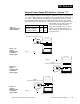
External Power Supply DIP Switches (Option “T”)
Models equipped with an external signal conditioner power supply (Option
“T”), have a DIP switch for selecting the power supply voltage. Output 2, 3
or 4 can be ordered with the external power supply. The location of each
board and DIP switch appear below. When the control leaves the factory,
both switches are off. The figures below show a PC board cutaway for each
DIP switch. See the table to the left
for the power supply switch set-
tings. The settings can be used for
all three output DIP switches. For
other voltage or current ratings con-
tact the factory.
Control Chassis - Top View
(Factory default is off)
Output 2
External Signal Conditioner Power Supply
PC Board Cutaway
O
N
12
Control Chassis - Top View
(Factory default is off)
Output 3
External Signal Conditioner Power Supply
PC Board Cutaway
O
N
12
Control Chassis - Top View
(Factory default is off)
Output 4
External Signal Conditioner Power Supply
PC Board Cutaway
O
N
12
Figure 1.5a -
Output 2
External Signal
Conditioner
Power Supply.
Figure 1.5b -
Output 3
External Signal
Conditioner
Power Supply.
Figure 1.5c -
Output 4
External Signal
Conditioner
Power Supply.
98 _ C - _ _ _ T - _ _ _ _
98 _ C - _ _ _ _ - T _ _ _
98 _ C - _ _ _ _ - _ T _ _
Voltage/Load Current S 1 S 2
5V ±5% @ 30mA On On
12V ±5% @ 30mA On Off
20V ±5% @ 30mA Off Off
Table 1.5 -
Power Supply DIP
Switch Settings.