
User`s manual


1.4 WATLOW Series 982 User’s Manual
Starting Out with the Watlow Series 982, Chapter 1
DIP Switches
The Hardware Lockout/Battery Backup DIP Switch
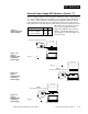
All units are equipped with a DIP switch for hardware lockout of the SEt
and Fcty prompt menus, and to enable battery backup of the Run parame-
ters. The location of the board and switch appear below. The switches are
clearly numbered, and are labeled on the outside of the board. When
Switch #1 is on, battery backup is enabled. When Switch #2 is on, the
menus under the SEt prompt (Input, Output, Global and
Communications) and Fcty prompt (Diagnostics and Calibration) cannot
be viewed. When the control leaves the factory switch #1 is on and switch
#2 is off.
Control Chassis
Top View (982 & 984)
Left-side View (981 & 983)
Lockout
DIP
On
Off
Figure 1.4 -
Battery backup and
hardware lockout
DIP switches.
battery backup of Run prompts or
lockout Setup and Factory menus or
O
N
↑
12
O
N
↑
12
O
N
↑
12
O
N
↑
12
Input
Output Global
Diagnostics Calibration
Commu-
nications
ç
CAUTION:
There is danger of
an explosion if the
battery is incorrect-
ly replaced. This
battery is factory
replaceable only.
Dispose of used
batteries according
to manufacturer’s
recommendations.