
User`s manual


WATLOW Series 982 User’s Manual 2.11
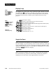
Installation and Wiring, Chapter 2
˜
NOTE:
Successful installa-
tion requires five
steps:
• Model number and
software choice
(Appendix);
• DIP switch set-
tings (Chapter 1);
• Sensor match
(Chapter 2 and
Appendix);
• Sensor installation
(Chapter 2); and
• Wiring (Chapter 2).
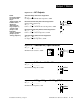
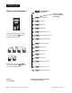
Figure 2.11a —
AC Outputs
Solid-state Relay with Contact Suppression
98 _ C - _ _ B _ - _ _ _ _
0.5 amps, minimum off-state impedance: 20KΩ
Electromechanical Relay with Contact Suppression
(NO and COM contacts only)
98 _ C - _ _ D _ - _ _ _ _
Form C, 5 amps, minimum off-state impedance: 20KΩ
Electromechanical Relay without Contact Suppression
98 _ C - _ _ E _ - _ _ _ _
Form C, 5 amps off-state impedance: 31MΩ
Solid-state Relay without Contact Suppression
98 _ C - _ _ K _ - _ _ _ _
0.5 amps, off-state impedance: 31MΩ
Output 1 Wiring
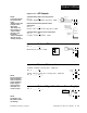
Figure 2.11b — Switched DC, Open Collector
98 _ C - _ _ C _ - _ _ _ _
Minimum load resistance: 500Ω
External
Load
COM
L1
L2
Fuse
NO
12
13
NC
14
(#14 for D & E outputs only)
12
External
Load
+
13
14
-
COM
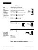
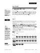
Figure 2.11d — 0-5V
ÎÎ
, 1-5V
ÎÎ
and 0-10V
ÎÎ
(DC) Process
98 _ C - _ _ F _ - _ _ _ _
Minimum load impedance: 1KΩ
Figure 2.11c — 0-20mA and 4-20mA Process
98 _ C - _ _ F _ - _ _ _ _
Maximum load impedance: 800Ω
14
-
+
12
14
-
+
13
+ Vdc
Internal Circuitry
12
13
14
790Ω
19 to 32VÎ (dc)