
User`s manual


WATLOW Series 982 User’s Manual 2.9
Installation and Wiring, Chapter 2
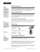
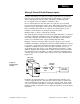
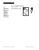
Input 2 Wiring
˜
NOTE:
Successful installa-
tion requires five
steps:
• Model number and
software choice
(Appendix);
• DIP switch set-
tings (Chapter 1);
• Sensor match
(Chapter 2 and
Appendix);
• Sensor installation
(Chapter 2); and
• Wiring (Chapter 2).
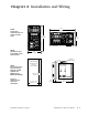
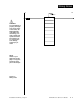
Figure 2.9a — Slidewire Feedback or Potentiometer Input
98 _ C - _ 3 _ _ - _ _ _ _
Slidewire resistance: 100 to 1,200Ω
19
20
18
CW
CCW
Wiper
˜
NOTE:
See Chapter 9 for
information on
slidewire feedback.
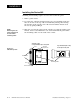
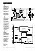
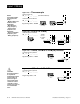
Figure 2.9b — Digital Event Input 2
98 _ C - _ 5 _ _ - _ _ _ _
0-3VÎ (dc) Event Input 2 off (open)
14-36VÎ (dc) Event Input 2 on (closed)
20
18
+5VÎ (dc)
100Ω
750Ω
4.7KΩ
1KΩ
.01µf
19
Internal Circuitry
1KΩ
20
18
20
19
+
-