
User`s manual

1/16 DIN 20
1/32 DIN 20
1/8 DIN Horizontal 20
1/8 DIN Vertical 20
Access Lockout 59
AC Line Frequency 23, 33, 64
Active Displays 23, 33, 68
Active Output Indicator Lights 20
Address 23, 34, 39, 66
Adjust the set point 21
Adjusting the set temperature 21
Advance Key 20
Advanced Control Algorithm 3
Agency Approvals 1, 72
Alarm 1 Hysteresis 23, 32
Alarm 1 Latching 23, 32
Alarm 1 Logic 23, 32
Alarm 1 Message 23, 32
Alarm 1 Silencing 23, 32
Alarm 1, 2, or 3 Silencing 64
Alarm 2 Hysteresis 23, 32
Alarm 2 Latching 23, 32
Alarm 2 Logic 23, 32
Alarm 2 Message 23, 32
Alarm 2 Silencing 23, 32
Alarm 3 Hysteresis 23, 33
Alarm 3 Latching 23, 33
Alarm 3 Logic 23, 33
Alarm 3 Message 23, 33
Alarm 3 Silencing 23, 33
Alarm High 1 Status 25
Alarm High 2 Status 25
Alarm High 3 Status 25
Alarm Hysteresis 39, 64
Alarm Latching 32, 33, 69
Alarm Low 1 Status 25
Alarm Low 2 Status 25
Alarm Low 3 Status 25
Alarm Message 21, 32, 33, 69
Alarm Set Points 64
Alarm Silencing 32, 64, 69
Alarm Features 64
Ambient Temperature 24, 54, 69, 70, 72
Ambient temperature error 70
Analog Output 1 Scale High 23, 29
Analog Output 1 Scale Low 23, 29
Analog Output 1 Units 23, 29
Analog Output 3 Scale High 23, 31
Analog Output 3 Scale Low 23, 31
Analog Output 3 Units 23, 31
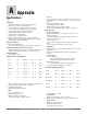
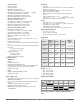
Appendix 71
Auto (closed loop) and Manual (open loop)
Control 21, 60
Auto (closed loop) control 21, 60
Auto-Manual Control Indicator Light 20
Automatic Mode 21, 60
Automatic Send Data control 18
Autotune 22, 35, 39, 58, 69
B&B Converter 18
Back Views 10
Baud Rate 3, 23, 34, 66
Biasing and termination 18
Calibration 24, 54, 55, 70
Calibration Offset 22, 35, 39, 59
Checksum error 70
Closed Loop 21, 60
Closed Loop Set Point 25
CMC Converter 18
Communications features 65
Communications specifications 72
Control Method 1 23, 28
Control Method 2 23, 30
Control Method 3 23, 31
Control Methods features 60
Current Ramp Set Point 25
Dead Band 36, 37, 39, 62
Dead Band Cool 37, 39, 62
Dead Band Heat 36, 39 ,62
Default Parameters 24, 54, 56
Derivative Cool 22, 37, 39, 62
Derivative Heat 22, 36, 39, 62
Derivative Term 37, 39
Deviation Alarms 21, 22, 23, 25, 27, 28, 30,
38, 39, 64
Dimensions 4, 5
1/16 DIN 4
1/32 DIN 4
1/4 DIN 5
1/8 DIN 5
Dimensions specifications 72
Display Intensity 54
Editing a profile 46
EIA/TIA-232 to EIA/TIA-485 Converter 18
EIA/TIA-485 11, 15, 18, 65, 66, 67
EIA/TIA-485 serial port 65, 66, 67
Elapsed Jump Count 46, 52
EM Gateway 19
End Set Point 32, 46, 52
End Step 41, 44, 46, 48, 52
Error condition 21, 70
Error Messages 70
Ethernet Gateway 19
Event outputs 22, 37, 39, 41, 42, 43, 46, 47,
48, 49, 50, 52
Event Outputs 1-3 22, 37, 39, 41, 42, 43,
46, 47, 48, 49, 50, 52
Event output status 52
Factory Page 24, 54
Factory Page Overview 24
Features and Benefits 3
Failed File Number 52
Failed Step Number 52
File 41, 45, 46
File Number 45, 46, 51
File Running 52
Filter Time Constant 59
Filter Value 23, 27, 59
Filtered Process Value 25
Fixed Time Base 1 23, 28
Fixed Time Base 2 23, 30
Fixed Time Base 3 23, 31
Functionality Matrix 72
Guaranteed Soak Deviation 48, 70
Guaranteed Soak Deviation Enable 23, 34,
51
Guaranteed Soak Deviation message 51
Guaranteed Soak Deviation Value 22, 23,
34, 51
Greenlee 4, 5
Heat Control Method 22, 35, 39, 60
Heat Hysteresis 22, 36, 39
High Range and Low Range 60
High Scale and Low Scale 60
Hold 21, 45, 46, 47, 48, 49, 50, 51
Hold a profile 45, 46, 47
Home Page 21, 25
Home Page Overview 21
IDC 67
Independent Heat and Cool PID 63
Infinity Key 20
INFOSENSE™ 1, 3, 26, 58
INFOSENSE™ 1, 2, 3, 4 26, 58
Infrared Communications 3, 72
Infrared Data Association 67
Infrared Data Communications 67
Input Accuracy 71
Input Error 23, 33, 60
Input Error Failure Mode 23, 33, 60
Input Error Latching 23, 33, 60
Input Error Power 23, 33
Input Filter 23, 27, 59
Input ranges 71
Inputs 58
inputs and outputs 2
Install and Wire 4
Installation
1/32 DIN 6
1/16 DIN 7
1/8 DIN 8
1/4 DIN 9
Integral Cool 22, 36, 39, 62
Integral Heat 22, 35, 39, 62
Integral Term 37, 39
IP65/NEMA 4X seal 6
IrDA 67, 72
Isolation 18
Isolation Blocks 11
Jump Count 44, 46, 47, 52
Jump Count Step Enabled 51
Jump File 44, 46, 52
Jump Loop Step 44, 48, 51, 52, 70
Jump Step 44, 50, 52
Keys and Displays 20
Latching Input Error 23, 33, 60
Latching Alarm 20, 32, 33, 64
Left Display 20
Link File 41, 44, 47, 52
Link File Step 44,47, 52
Lockout 23, 34, 59, 69
Lower Display 20
Manual (open loop) Control 21, 60
Manual Mode 21, 60
Manual Tuning 58, 69
Master Step Chart 49, 50
Maximum Recorded Ambient Temperature
24, 54
Measured Value 25
Minimum Recorded Ambient Temperature
24, 54
Modbus Device Address 23, 34
Modbus Network 66
Modbus RTU protocol 66
Model Numbers 73
Monitor profile status from Modbus 52
National Electric (NEC) 11
Watlow Series SD ■ 74 ■ Appendix
Index