
User`s manual

Watlow Series SD ■ 72 ■ Appendix
Solid-state Relay
• Optically isolated
• Zero cross switched
•Without contact suppression
• Minimum load current: 10 mA rms
• Maximum current: 0.5A rms at 24 to 240VÅ (ac), resistive
• 20 VA pilot duty, 120/240VÅ (ac), inductive
• Must use RC suppression for inductive loads
• Maximum offstate leakage current: 100 µA rms
Electromechanical Relay, Form A
• Minimum load current: 10 mA
•2 A@ 240VÅ (ac) or 30VÎ (dc) maximum, resistive
• 125 VA pilot duty, 120/240VÅ (ac), inductive
• Must use RC suppression for inductive loads
• Electrical life 100,000 cycles at rated current
Electromechanical Relay, Form C
• Minimum load current: 10 mA
•5 A@ 240VÅ (ac) or 30VÎ (dc) maximum, resistive
• 125 VA pilot duty, 120/240VÅ (ac), inductive
• Must use RC suppression for inductive loads
• Electrical life 100,000 cycles at rated current
Process *
• Range selectable: 0 to 20 mA, 4 to 20 mA, 0 to 5VÎ (dc), 1 to
5VÎ (dc), 0 to 10VÎ (dc)
• Reverse or direct acting
•0 to 10VÎ (dc) voltage output into 1,000 Ω minimum load resist-
ance
•0 to 20 mA current output into 800 Ω maximum load resistance
• Resolution:
dc ranges: 2.5 mV nominal
mA ranges: 5 µA nominal
• Calibration accuracy:
dc ranges: ±15 mV
mA ranges: ±30 µA
•Temperature stability: 100 ppm/°C
Communications
EIA/TIA-485
• Isolated
• Modbus™ RTU protocol
• 9600, 19200 and 38400 baud rates
•Amaximum of 32 units can be connected (with additional 485
repeater hardware, up to 247 units may be connected)
• Sampling rate: 20 Hz
IrDA
• Modbus™ RTU via IRCOMM over IrDA
• Sampling rate: 20 Hz
Agency Approvals
•ULListed Process Control UL3121
®
(UL 61010C-1), c-UL, IP65
(NEMA 4X). File # E185611.
UL
®
is a registered trademark of the Underwriter’s Laborato-
ries, Inc.
• CE approved. See Declaration of Conformity.
• CSA approved C22.2#24, File 158031
• NSF 2 approved for type E, J, K, T and RTD sensors, File
49660-0002-000.
Terminals
•Touch-safe
• Input power and control outputs: 0.2 to 4 mm
2
(22 to 12 AWG), 6
mm (0.25 in) strip length
• Sensor inputs and process outputs: 0.1 to 0.5 mm
2
(28 to 20
AWG), 8 mm (0.30 in) strip length
• Solid or tinned wire recommended for spring clamp style con-
nectors.
•Torque: terminal blocks 1 to 6 (SD _ _ - _ [C, K or J] _ _ - _ _ _ _)
and 1 to 4 (SD _ _ - _ F _ _ - _ _ _ _ ) are 0.8 Nm (7 in-lb); termi-
nal blocks 12, 13, and 14 are 0.9 Nm (8 in-lb).
Power
• 100 to 240VÅ (ac) +10%; -15%; 50/60 Hz, ±5%
• 24V‡ (ac/dc) +10%; -15%; 50/60 Hz, ±5%; Class 2 power source
is required for low-voltage model.
• 10VA maximum power consumption
• Data retention upon power failure via nonvolatile memory
Operating Environment
• -18 to 65°C (0 to 149°F)
•0 to 90% RH, non-condensing
• Storage temperature: -40 to 85°C (-40 to 185°F)
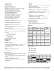
Dimensions
Weight
(approximate)
• SD3 - 75 g (0.16 lbs)
• SD6 - 100 g (0.22 lbs)
• SD8 - 145 g (0.32 lbs)
• SD4 - 200 g (0.43 lbs)
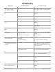
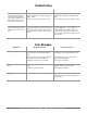
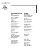
Functionality Matrix
Note: These specifications are subject to change without prior
notice.
DIN Size
Behind
Panel
(max.)
Width Height
1/32
97.8 mm
(3.85 in)
52.6 mm
(2.07 in)
29.7 mm
(1.17 in)
1/16
97.8 mm
(3.85 in)
52.1 mm
(2.05 in)
52.1 mm
(2.05 in)
1/8 Vertical
97.8 mm
(3.85 in)
52.8 mm
(2.08 in)
99.8 mm
(3.93 in)
1/8
Horizontal
97.8 mm
(3.85 in)
99.8 mm
(3.93 in)
52.8 mm
(2.08 in)
1/4
101.1 mm
(3.98 in)
99.8 mm
(3.93 in)
99.8 mm
(3.93 in)
Universal
Input
Control Alarm Process 485 Comm
Input 1
Output 1
Output 2
Output 3
Display
Height
(in.)
L- 7.6 mm (0.30)
R - 5.6 mm (0.22)
U -10.2 mm (0.40)
L- 6.1 mm (0.24)
U -10.2 mm (0.40)
L- 6.1 mm (0.24)
U -10.2 mm (0.40)
L- 6.1 mm (0.24)
U -14.2 mm (0.56)
L -10.2 mm (0.40)