
User`s manual


6. Test the communications.
Once communications is configured, test the link to
the controller for verification that everything is wired
and configured properly. Check the wiring and configu-
rations if things aren’t working. One misplaced wire or
one incorrect setting will keep communications from
working. When using an EIA-232 to EIA-485 converter,
be sure to follow the configuration instructions provided
with the converter, as some may require special
jumper/switch settings, external power supply require-
ments or special signals from the software. Some soft-
ware packages have built-in routines for testing the
communications or use Comm7 to help diagnose prob-
lems.
7. Start communications with the controller.
With the communications successfully verified, the
software is now ready for use with the controller. The
above guidelines are the general steps to establishing
communications with controllers using Modbus. Some
applications may require other steps not mentioned, but
would follow the same general process.
8. Programming and configuring the controllers.
When programming and configuring the controllers
with a software program, a couple of things must be
kept in mind. If the software allows changing Setup pa-
rameters such as Input Type, other parameter values
that are dependent on that setting may be automatical-
ly changed. Some software packages may warn you of
this possibility and others may not.
Also, some controllers require that any changes
made by the software program to controller parameters
that need to be retained in the controller memory must
be saved in the non-volatile memory writes register. Any
settings not saved to controller memory will be lost
when the controller’s power is turned off.
Writing to Non-Volatile Memory
The Series SD stores parameter values in non-
volatile EEPROM memory. This type of memory has a
finite life of approximately 100,000 write cycles. In some
applications, you might need to constantly write new
values to a particular register. Examples might be the
writing of ramping set points or repetitive loops through
serial communications. Continuous writes may result in
premature controller failure and system downtime.
To prevent premature failure of the EEPROM when
frequently writing register values, write a 0 to register
17. Any values written after that, will not be stored to
EEPROM. However, this data is lost when power is re-
moved. Register 17 defaults to a value of 1 after each
power cycle, writing values to EEPROM again. You
must write a 0 to register 17 upon power up to prevent
data from being written to EEPROM.
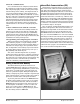
Infrared Data Communications (IDC)
Infrared Data Communications is an option avail-
able on the 1/16th, 1/8th and 1/4 Din Series SD prod-
ucts. This option supports wireless communications
with PDAs (personal digital assistants) or other devices
equipped with infrared communications that support
the IrDA 1.0 Standard. IrDA is an acronym for the In-
frared Data Association, www.irda.org. A PDA or other
master device communicates with the SD Series using
Modbus ASCII via IRCOMM over IrDA. IDC supports
wireless communications through transparent material
to a distance of no less than one meter between devices
at a maximum angle of 15 Degrees.
IDC can support complete Series SD parameter con-
figuration and operation. The actual user interface or
configuration is dependent on the master device (PDA)
application software. A source for this software is In-
stant HMI from Software Horizons. For more informa-
tion, go to www.InstantHMI.com or call (978) 670-8700.
Advantages of this feature include automated logging of
key process variables, increased accuracy and ease of
use for recipe or configuration setups, and easier con-
troller data exchange in physically restricting environ-
ments, such as semiconductor clean rooms. This feature
reduces the use of paper to record instrument informa-
tion as well as human transposition errors.
Watlow Series SD ■ 67 ■ Chapter 10 Features