
User`s manual
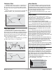


put is distributed in groupings of three ac line cycles.
For each group of three ac line cycles, the controller de-
cides whether the power should be on or off. There is no
fixed cycle time since the decision is made for each
group of cycles. When used in conjunction with a zero
cross (burst fire) device, such as a solid-state power con-
troller, switching is done only at the zero cross of the ac
line, which helps reduce electrical noise (RFI).
Variable time base should be used with solid-state
power controllers, such as a solid-state relay (SSR) or sili-
con controlled rectifier (SCR) power controller. Do not use
a variable time base output for controlling electromechani-
cal relays, mercury displacement relays, inductive loads or
heaters with unusual resistance characteristics.
The combination of variable time base output and a
solid-state relay can inexpensively approach the effect of
analog, phase-angle fired control.
You must select the AC Power line frequency, 50 or 60 Hz.
Single Set Point Ramping (static set point version
only SD_C- _ _ _ _- ____)
Ramping protects materials and systems that cannot
tolerate rapid temperature changes. The value of the
ramp rate is the maximum degrees per minute or hour
that the system temperature can change.
Select Ramping Mode [``rP] (Setup Page):
[`OFF] ramping not active.
[`Str] ramp at startup.
[``On] ramp at startup or when the set point
changes.
Select whether the rate is in degrees per minute or
degrees per hour with Ramp Scale [rP;sc] (Setup Page).
Set the ramping rate with Ramp Rate [rp;rt] (Setup
Page).
Alarms
Alarms are activated when the process value or tem-
perature leaves a defined range. A user can configure
how and when an alarm is triggered, what action it
takes and whether it turns off automatically when the
alarm condition is over.
Configure alarm outputs in the Setup Page before
setting alarm set points.
Process or Deviation Alarms
A process alarm uses one or two absolute set points
to define an alarm condition.
A deviation alarm uses one or two set points that are
defined relative to the control set point. High and low
alarm set points are calculated by adding and/or sub-
tracting offset values from the control set point. If the
set point changes, the window defined by the alarm set
points automatically changes with it.
Select the alarm type with the Setup Page parame-
ters. View or change process or deviation set points with
the Operations parameters.
Alarm Set Points
The alarm high set point defines the process value or
temperature that will trigger a high side alarm. It must
be higher than the alarm low set point and lower than
the high limit of the sensor range.
The alarm low set point defines the temperature
that will trigger a low side alarm. It must be lower than
the alarm high set point and higher than the low limit
of the sensor range.
View or change alarm set points with the Operations
parameters.
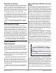
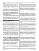
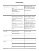
Set Point
Time
Temperature
Temperature ramps to Set Point at a set rate
degrees
per minute
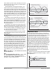
Set Point
Time
Temperature
Temperature reaches Set Point quickly
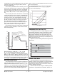
66 percent output
6 ON, 3 OFF
50 percent output
3 ON, 3 OFF
100 percent output
10 ON, 0 OFF
Watlow Series SD ■ 64 ■ Chapter 10 Features