
User`s manual


would result in an actual output power level of 50%. But
if the PID calculated power output is 100%, then the
power level will be 70%.
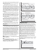
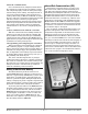
Power scaling establishes the maximum power out-
put and the minimum power output. The output power
is then linearly scaled within that range. The default
values of Output Power Scale Low of 0% and Output
Power Scale High of 100% in effect disable power scal-
ing.
Linear scaling allows the controller to do calculations
over the full range of power (0 to 100%) and adjust that
calculation within the actual output span. For instance,
if scale low is set to 15% and scale high is set to 80%,
the output power will always be between 15 and 80%. If
the PID calculation is 100%, the output power will be
80%, which is the same result you would get from a
power limit of 80%. However, if the PID calculation for
heat is 50%, the output will be 50% of the allowable
range, which scales to an actual output of 47.5%.
Power limiting and power scaling affect the specified
output at all times, including in on-off control, manual
mode and autotuning.
The Power Limit 1, 2 and 3 ([PL`1], [PL`2] and
[PL`3]) and Output Power Scale Low 1, 2 and 3
([PSL1], [PSL2] and [PSL3]) and Output Power Scale
High 1, 2 and 3 ([PSH1], [PSH2] and [PSH3]) appear in
the Setup Page. The calculated PID heat and cool power
values can be viewed with Power Heat [Po;ht] and Pow-
er Cool [Po;CL] parameters in the Operations Page.
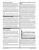
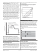
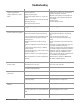
Non-linear output curve
A non-linear output curve may improve performance
when the response of the output device is non-linear. If
Output Non-linear Function is set to curve 1 [Cru1] or
curve 2 [Cru2], a PID calculation yields a lower actual
output level than the linear output provides. These out-
put curves are used in plastics extruder applications.
Curve 1 is for oil cooled extruders and curve 2 is for wa-
ter cooled extruders.
Change the linearity for each output with Output
Non-linear Function 1, 2 or 3 ([nLf1], [nlf2] or
[nlf3]) in the Setup Page.
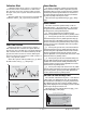
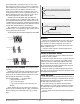
Independent Heat and Cool PID
In an application with one output assigned to heating
and another assigned to cooling, each will have a sepa-
rate set of PID parameters and separate dead bands.
The heating parameters take effect when the process
temperature is lower than the set point and the cooling
parameters take effect when the process temperature is
higher than the set point.
Adjust heat and cool PID parameters are Operations
parameters.
Variable Time Base
Variable time base is the preferred method for con-
trolling a resistive load, providing a very short time base
for longer heater life. Unlike phase-angle firing, vari-
able-time-base switching does not limit the current and
voltage applied to the heater.
With variable time base outputs, the PID algorithm
calculates an output between 0 and 100%, but the out-
Time
Temperature
Set Point
Heating Side Proportional Band
Heating Side Dead Band
Cooling Side Dead Band
Cooling Side Proportional Band
Actual Output Power
0
20
40
60
80
100
PID Calculation
Linear
Curve 1
Curve 2
100
90
80
70
60
50
40
30
20
10
0
Percent Power Output
Time ➔
Power Limit 100%
Power Scale Low 0%
Power Scale High 100%
Power Limit 100%
Power Scale Low 15%
Power Scale High 80%
Power Limit 70%
Power Scale Low 0%
Power Scale High 100%
Power Limit 70%
Power Scale Low 15%
Power Scale High 80%
Watlow Series SD ■ 63 ■ Chapter 10 Features