
User`s manual


High Scale and Low Scale
When an analog input is selected as process voltage
or process current input, you must choose the value of
voltage or current to be the low and high ends. For ex-
ample, when using a 4 to 20 mA input, the scale low
value would be 4.00 mA and the scale high value would
be 20.00 mA. Commonly used scale ranges are: 0 to 20
mA, 4 to 20 mA, 0 to 5V, 1 to 5V and 0 to 10V.
The Series SD allows you to create a scale range for
special applications other than the standard ones listed
above. Reversing of the scales from high values to low
values is permitted for analog input signals that have a
reversed action. For example, 50 psi = 4 mA and 10 psi
= 20 mA.
Select the low and high values with Process Scale
Low [Sc;lo] and Process Scale High [Sc;hi] (Setup
Page).
High Range and Low Range
With a process input, you must choose a value to
represent the low and high ends of the current or volt-
age range. Choosing these values allows the controller’s
display to be scaled into the actual working units of
measurement. For example, the analog input from a hu-
midity transmitter could represent 0 to 100 percent rel-
ative humidity as a process signal of 4 to 20 mA. Low
scale would be set to 0 to represent 4 mA and high scale
set to 100 to represent 20 mA. The indication on the dis-
play would then represent percent humidity and range
from 0 to 100 percent with an input of 4 to 20 mA.
Select the low and high values with Units Scale Low
[rg;Lo] and Units Scale High [rg;hi] (Setup Page).
Control Methods
Output Configuration
Each controller output can be configured as a heat
output, a cool output, an alarm output or deactivated.
No dependency limitations have been placed on the
available combinations. The outputs can be configured
in any combination. For instance, all three could be set
to cool.
Analog outputs can be scaled for any desired current
range between 0 and 20 mA or voltage range between 0
to 10V. The ranges can be reversed to high-to-low for re-
verse acting devices.
Heat and cool outputs use the set point and Opera-
tions parameters to determine the output value. All
heat and cool outputs use the same set point value.
Heat and cool each have their own set of control param-
eters. All heat outputs use the same set of heat control
parameters and all cool outputs use the same set of cool
output parameters.
Each alarm output has its own set of configuration
parameters and set points, allowing independent opera-
tion.
Auto (closed loop) and Manual (open loop)
Control
The controller has two basic modes of operation, auto
mode and manual mode. Auto mode allows the con-
troller to decide whether to perform closed loop control
or to follow the settings of the Input Error Failure Mode
parameter (Setup Page). The manual mode only allows
open loop control. The Series SD controller is normally
used in the auto mode. The manual mode is usually on-
ly used for specialty applications or for troubleshooting.
Manual mode is open loop control that allows the
user to directly set the power level to the controller’s
output load. No adjustments of the output power level
occur based on temperature or set point in this mode.
In auto mode, the controller monitors the input to
determine if closed loop control is possible. The con-
troller checks to make certain a functioning sensor is
providing a valid input signal. If a valid input signal is
present, the controller will perform closed loop control.
Closed loop control uses a process sensor to determine
the difference between the process value and the set
point. Then the controller applies power to a control out-
put load to reduce that difference.
If a valid input signal is not present, the controller
will indicate an input error message [Er;In] and then
use the Input Error Failure Mode [faIl] setting to de-
termine operation. You can choose to have the controller
perform a “bumpless” transfer, switch power to output a
preset manual level, or turn the output power off.
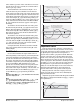
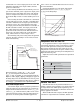
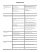
Bumpless transfer will allow the controller to trans-
fer to the manual mode using the last power value cal-
culated in the auto mode if the process had stabilized at
a ±5 percent output power level for two minutes prior to
sensor failure, and that power level is less than 75 per-
cent.
Input Error Latching [I;Err] (Setup Page) deter-
mines the controller’s response once a valid input signal
returns to the controller. If latching is on [`Lat], then
the controller will continue to indicate an input error
until the error is cleared. To clear a latched alarm, press
the Infinity Key ˆ. If latching is off [nLAt], the con-
troller will automatically clear the input error and re-
turn to reading the temperature. If the controller was in
the auto mode when the input error occurred, it will re-
Time
Temperature
40%
Sensor
Break
2 minutes
Locks in
Output
Power
0%
Set Point
Actual Temperature
Output Power
Power
100%
Watlow Series SD ■ 60 ■ Chapter 10 Features