
User`s manual


Watlow Series SD ■ 59 ■ Chapter 10 Features
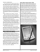
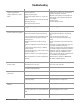
Calibration Offset
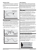
Calibration offset allows a device to compensate for
an inaccurate sensor, lead resistance or other factors
that affect the input value. A positive offset increases
the input value, and a negative offset decreases the in-
put value.
The input offset value can be viewed or changed with
Calibration Offset [`CAL] (Operations parameters).
Filter Time Constant
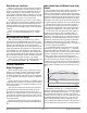
Filtering smoothes an input signal by applying a
first-order filter time constant to the signal. The dis-
played value, the controlled value or both the displayed
and controlled values can be filtered. Filtering the dis-
played value makes it easier to monitor. Filtering the
signal may improve the performance of PID control in a
noisy or very dynamic system.
Select filter options with Input Filter [Ftr;E]. Select
the Filter Value with [FLtr] (Setup Page).
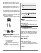
Sensor Selection
You need to configure the controller to match the input
device, which is normally a thermocouple, RTD or process
transmitter. When you select an input device, the controller
automatically sets the input linearization to match the sen-
sor. It also sets high and low limits, which in turn limit the
set point range-high and range-low values.
Select the sensor type with Sensor Type [`Sen] (Setup
Page).
Access Lockout
The user’s access to the Operations Page can be con-
trolled through the [`lOC] parameter. The [`lOC] parame-
ter appears at the end of the Setup Page. It does not affect
the Setup, Factory or Programming Pages.
[``0] All the Operations Page parameters may be
viewed or changed. Full access to profiles on profiling version.
[``1] The set point, process value, auto-manual selection
and alarm settings are the only visible Operations Page pa-
rameters. Set point is adjustable in this level. Auto-manual
selection and autotune are permitted. During manual opera-
tion, the percent power is adjustable. Full access to profiles
on profiling version.
[``2] The set point, process value, auto-manual selection
and alarm settings are the only visible Operations Page pa-
rameters. Set point is adjustable in this level. Auto-manual
selection is permitted. During manual operation, percent
power is adjustable. Can run profiles, but cannot enter or edit
profile information on profiling version.
[``3] The set point, process value and alarm settings are
the only visible Operations Page parameters. Set point is ad-
justable. Auto-manual selection is not permitted. During
manual operation, percent power is adjustable. No access to
profile functions on profiling version.
[``4] The set point and process values are the only visible
Operations Page parameters, set point is not adjustable. Dur-
ing manual operation, percent power is not adjustable. No
access to profile functions on profiling version.
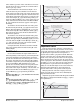
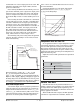
Set Point Low Limit and High Limit
The controller constrains the set point to a value between
a SP low limit and a SP high limit. Note: To stop the Series
SD controller from controlling to a set point, press the Down
Key while the set point value is equal to the SP.Lo setting.
[Off] will be displayed in the lower display and the controller
will no longer attempt to maintain a set
Set the set point range with Set Point Low [SP;Lo] and
Set Point High [SP;hi] (Setup Page).
Set Point Range (must be between Range High and Range Low)
Low Limit of selected Sensor Range
High Limit of selected Sensor Range
Temperature
Range High Range (between High Limit of Sensor and Range Low)
Range Low Range (between Low Limit of Sensor and Range High)
Range Low
Range High
Unfiltered Input Signal
Time
Temperature
Filtered Input Signal
Time
Temperature
Time
Temperature
Temperature Reading
from Sensor
Actual Process Temperature
Negative Calibration Offset will
compensate for the difference
between the Sensor Reading and
the Actual Temperature