
User`s manual


Watlow Series SD ■ 3 ■ Chapter 1 Overview
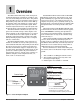
Features and Benefits
INFOSENSE™ Technology
• Improves sensor accuracy by a minimum of 50%.
User Definable Menu System
• Simplifies operator interface
User Definable Default Settings
• Restores to user defined controller settings
WATVIEW™ Software
• Operation, configuration and data logging with a
standard Windows
®
PC.
Infrared Communications
• Facilitates controller setup, operation and moni-
toring.
Up to three outputs (1/32 DIN two outputs only)
• Application versatility.
• Configuration flexibility.
Dual Displays on all models
• Better monitoring of process changes.
Ramp to Set Point
• Controls the rate of temperature changes.
Profiling (ramp and soak) Capability
•4 Profiles with 10 steps each
• Profiles can be linked together
• wait-for Process
• Guaranteed Soak
• Programmable Event Outputs
• Customer/OEM Profile save/restore
Available in an FM-approved limit version.
How to use the Series SD controller
Before you use your Series SD controller, it must be
installed and configured correctly. The setup steps you
need to perform will depend on how you will use it.
If you purchased the controller to design into your
products:
You will need to do the first three steps and maybe
some of the fourth step. Some wiring, such as the final
wiring of a communications connection or an alarm out-
put for signaling an external device, might be left to the
end user. In highly specialized applications with little
variation in operation and heat load, the OEM might con-
figure almost all the parameters.
If you purchased the controller to design and in-
stall into new equipment for your own use or to
retrofit into existing equipment:
You will need to complete all four steps.
If you purchased the controller installed in equip-
ment designed around it:
You will probably only need to do the fourth step. In
some instances, you may need to wire it for serial com-
munications and/or an alarm output. Some serial commu-
nications parameters on the Setup Page may need to be
changed.
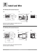
Step 1: Mount and install the controller.
The Series SD controller is designed to be panel
mounted in a standard DIN opening. The Series SD is
available in 1/32 DIN, 1/16 DIN, 1/8 DIN-horizontal, 1/8
DIN-vertical and 1/4 DIN sizes. Cut the correct size hole
into the panel and mount the controller, using its mount-
ing brackets. See Chapter Two for details on installation
and mounting.
If you retrofit the Series SD controller into an existing
application, you may need to modify an existing opening,
either by cutting it larger for a larger controller or using a
Watlow adapter plate to adapt it to a smaller controller.
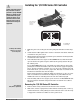
Step 2: Wire the controller.
The controller will need to have its power, input and
output wiring installed. The wiring depends on the specif-
ic model number of the Series SD controller. The dimen-
sion illustrations in Chapter Two show the location of the
model number on each DIN size. Use the model number
to determine which wiring diagrams to follow for your
controller. See Chapter Two for wiring details.
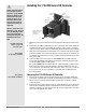
Step 3: Configure the Setup Page.
Setup Page parameters tell the controller what input
and output devices are wired to the controller and how
the controller should function. Without the proper Setup
Page settings, the controller will not operate or could op-
erate erratically. Since these settings require detailed
knowledge on the wiring and operation of the equipment,
the OEM or the designer normally programs these pa-
rameters. Some settings, such as the baud rate or con-
troller address, are Setup Page parameters, but would
probably be set by the end user.
These settings should be recorded for future reference.
The settings can also be stored using the [Usr;S] parame-
ter, on the Factory Page. For saving and restoring param-
eters, see Chapter Eight, Features. For details on config-
uring the Setup Page, see Chapter Five, Setup Page.
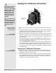
Step 4: Configure the Operations Page.
The Operations Page contains the parameters that
the equipment operator may need to set or change from
time to time. This includes calibration offset, autotune,
PID parameters and alarm set points. In some cases the
OEM manufacturer may set most of these parameters
because the equipment operates with little variation. In
equipment where demands could vary significantly, the
OEM may leave parameter adjustments to the end user.
The Operations Page on the Series SD controller is
customizable so that only the parameters that the opera-
tor may need to use will appear in the display. Settings
that won’t need to be adjusted can be hidden from the op-
erator, using the Programming Page. For more details on
the Programming Page, see Chapter Eight, Features. For
details on configuring parameters in the Operations
Page, see Chapter Six, Operations Parameters Tables.
Once you have verified the controller is operating proper-
ly, be sure to document all of your parameter settings.
Each parameter table has a settings column for
you to write in your values.