
User`s manual


Watlow Series SD ■ 25 ■ Chapter 4 Home
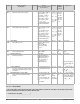
Display Parameter Name
Description
Settings Range
(Integer values for Modbus
in parenthesis.)
Default Modbus*
(less 40,001
offset)
Read/Write
Appears if:
4
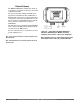
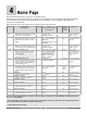
Home Page
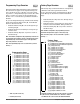
Press the Infinity Key ˆ at any time to go to the Home Page.
Depending upon the controller’s status, you will see some combination of the parameters listed below. Normally,
you will see the Process Value in the upper display and the Set Point in the lower display. See Home Page
Overview in Chapter Three.
After 60 seconds with no key presses, the controller reverts to the Home Page.
Measured
Value
Process Value
Displays the current process value in the
upper (left in 1/32 DIN) display.
-1999 to 9999
degrees or units
(-1999000 to 9999000)
NA
*20, 21 R
There is no input error
and [Ftr;E] is set to
[`Off] or [CntL].
Set Value Closed Loop Set Point
Show the current closed loop control set
point in the lower (right in 1/32 DIN)
display.
Set Point Low Limit
[SP;Lo]
to Set Point High
Limit
[SP;hi]
[OFF]
Stop controlling to SP
(-200000001)
75
*27, 28
R/W
Control mode is
[auto] and there is no
input error.
Measured
Value
Filtered Process Value
Displays the current filtered process val-
ue in the upper (left in 1/32 DIN) display.
-1999 to 9999
degrees or units
(-1999000 to 9999000)
NA
*22, 23 R
There is no input error
and [Ftr;E] is set to
[Disp] or [both].
Set Value Open Loop Output Power
Show the current open loop (manual)
control set point in the lower (right in
1/32 DIN) display.
The % indicator light is on when the con-
troller is in open loop (manual control).
-100.0 to 0.0% if any output
is set to cool; 0.0 to 100.0%
if any output is set to heat
(-10000 to 0000, 0000 to
10000. Two decimal places
implied for Modbus.)
0.0%
26 R/W
Control mode is
[Man]. If there is no
input error and [Ftr;E]
is set to [`Off] or
[Cont].
[``rP]
Current Ramp Set Point**
The current working control set point for
the ramp that is in process appears in
the lower (right in 1/32 DIN) display af-
ter this prompt appears.
-1999 to 9999
(-1999000 to 9999000)
NA
*254 255 R
Static set point version
only. and ramp to set
point active.
(SD _C - _ _ _ _ - _ _ _ _ )
[rP;tg]
Ramp Target Set Point**
The target set point for the ramp that is
in process appears in the lower (right in
1/32 DIN) display after this prompt ap-
pears.
Set Point Low Limit
[SP;Lo]
to Set Point High
Limit
[SP;hi]
NA
Same as
Closed
Loop Set
Point
Static set point version
only. and ramp to set
point active.
(SD _C - _ _ _ _ - _ _ _ _ )
[Er;In]
Input Error
Indicate an input error state.
None (0)
[----]
Error (1)
NA
24 R
There is an analog in-
put error.
[A1;Lo]
Alarm Low 1 Status
Indicate a low alarm at output 1.
None (0)
Alarm (1)
NA
29 R
There is an Alarm 1
low side alarm.
[A1;hi]
Alarm High 1 Status
Indicate a high alarm at output 1.
None (0)
Alarm (1)
NA
30 R
There is an Alarm 1
high side alarm.
[A2;Lo]
Alarm Low 2 Status
Indicate a low alarm at output 2.
None (0)
Alarm (1)
NA
31 R
There is an Alarm 2
low side alarm.
[A2;hi]
Alarm High 2 Status
Indicate a high alarm at output 2.
None (0)
Alarm (1)
NA
32 R
There is an Alarm 2
high side alarm.
[A3;Lo]
Alarm Low 3 Status
Indicate a low alarm at output 3.
None (0)
Alarm (1)
NA
33 R
There is an Alarm 3
low side alarm.
[A3;hi]
Alarm High 3 Status
Indicate a high alarm at output 3.
None (0)
Alarm (1)
NA
34 R
There is an Alarm 3
high side alarm.
Note: Some values will be rounded off to fit in the four-character display. Full values can be read with Modbus. All temperature parame-
ters are in °F through Modbus.
* Low register numbers contain the two higher bytes; high register numbers contain the two lower bytes of the four-byte integer. Decimal
precision is implied at three decimal places unless otherwise noted.
** Static set point version only (SD_C-_ _ _ _- _ _ _ _ ).