
User`s manual


Watlow Series SD ■ 18 ■ Chapter 2 Install and Wire
When choosing an EIA/TIA 232 to 485 converter, look for
one with the following features:
Two-wire capability
EIA/TIA-485 can be implemented as a two-wire sys-
tem or a four-wire system. Most Watlow controllers,
including the Series SD, use two-wire communica-
tions when working with EIA/TIA-485. The convert-
er selected must have a two-wire mode. Some con-
verters can only be used in a four-wire mode.
Automatic Send Data control
In a two-wire system, both the transmitted signals
and the received signals travel over the same pair of
wires, so the converter must have a method of
changing from the transmit mode to the receive
mode. Some converters require the toggling of a con-
trol line (usually the RTS line) to perform this tran-
sition, while others use an automatic timing circuit.
The toggling method is dependent on the PC soft-
ware to toggle the control line and the PC’s operating
system to make that transition happen in a timely
manner. Because of these dependencies, the best
choice for a converter is one with automatic control.
Isolation
Converters are available with or without input-to-
output isolation. An isolated converter is not a re-
quirement when used with the Series SD, but it is
recommended to avoid ground loops. Isolation could
be a consideration when the Series SD will be used
on a network with other devices that may require
isolation.
Power Supply
Many converters can be powered up either through
the signals of a serial port or through an external
power supply. Because some computers, such as lap-
tops, do not always provide enough power to supply
the converter, we recommend using an external pow-
er supply with specifications as recommended by the
converter manufacturer. Isolated converters may re-
quire two supplies.
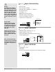
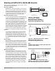
Biasing and termination
If the system does not work properly, it may need
termination resistors at each end of the network. A
typical installation would require a 120-ohm resistor
across the transmit/receive terminals (3 and 4) of the
last controller in the network and the converter box.
Pull-up and pull-down resistors may be needed at
the converter to maintain the correct voltage during
the idle state. The pull-up resistor is connected be-
tween the positive of the DC supply and the T+/R+
terminal. The pull-down resistor is connected be-
tween the negative of the DC supply and the T-/R-
terminal.
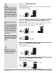
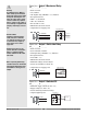
Selecting an EIA/TIA-232 to EIA/TIA-485 Converter
Figure 18a — B&B Converters
Isolated Converter - 4850I9TB
Non-Isolated Converter - 485SD9TB
B&B Electronics Manufacturing Company,
(815) 433-5100, http://www.bb-elec.com/
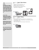
Figure 18b — CMC Non-Isolated Converter - ADA485L
CMC Connecticut Micro-Computer, Inc.,
1-800-426-2872, http://www.2cmc.com/
NOTE:
The CMC converter requires an external power supply when
used with a laptop computer.
Figure 18c — Wiring bias and termination resistors.
Controllers must be wired in a daisy chain configuration.
Add a 120Ω termination resistor on the last controller.
B
A
GND
T+/R+
T-/R-
1KΩ
120Ω
1KΩ
SD
SD SD
120Ω
EIA/TIA 485
Converter
Power Supply
DC
-VÎ
+VÎ
+VÎ-VÎ
3
3
3
44
4
9V (dc) (see note)
120V (ac)
COM.
T+/R+
T- /R-
EIA-232
ADA485L
EIA-485
A
B
A
B
G
9V
G
DI/ODI/O
3
4
7-ft. comms cable -
Watlow p/n 0219-0217-0000
T-/R-
TD (A)
TD (B)
T+/R+
120V (ac)
Power
Supply
+
–
GND
4
3
485SD9TB
GND
12V (dc)
Watlow p/n 0830-0473-0002
Watlow p/n 0830-0473-0001
6 ft. comms cable -
Watlow p/n 0830-0473-0003