
User`s manual


ç
Warning:
Use National Electric (NEC) or
other country-specific standard
wiring and safety practices when
wiring and connecting this con-
troller to a power source and to
electrical sensors or peripheral
devices. Failure to do so may re-
sult in damage to equipment and
property, and/or injury or loss of
life.
Quencharc Note:
Switching pilot duty inductive
loads (relay coils, solenoids,
etc.) with the mechanical relay
or solid-state relay output op-
tions requires use of an R.C.
suppressor.
Watlow carries the R.C. sup-
pressor Quencharc brand name,
which is a trademark of ITW
Paktron. Watlow Part No. 0804-
0147-0000.
Note: To prevent ground loops,
isolation needs to be maintained
from input to output when using
switched DC or analog process
outputs.
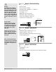
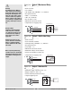
Figure 16a — Output 3 Mechanical Relay
SD_ _ - _ _ _ E - _ _ _ _
• Form A contact
• 5 A, resistive
• 125 VA pilot duty, 120/240VÅ (ac), inductive
• See Quencharc note.
• 240VÅ (ac) maximum.
• 30VÎ (dc) maximum.
• For use with ac or dc.
• Minimum load current 10 mA
• Output does not supply power.
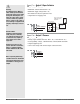
Figure 16b — Output 3 Solid-state Relay
SD_ _ - _ _ _ K - _ _ _ _
• Form A contact
• 0.5 A maximum, resistive
• 20 VA pilot duty, 120/240VÅ (ac), inductive
• See Quencharc note.
• 24 to 240VÅ (ac).
• Minimum load current 10 mA
• Maximum leakage current 100 µA
• Not for use with direct current (dc).
• Output does not supply power.
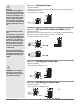
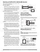
Figure 16c — Output 3 Switched DC
SD_ _ - _ _ _ C - _ _ _ _
• Maximum supply current 30 mAÎ (dc).
• Supply voltage 6 to 12VÎ (dc).
• Not for switching mechanical relays.
• Output supplies power.
Internal Circuitry
dc-
dc+
6 to 12VÎ (dc)
Load
Switched DC
-
+
12
13
12 dc +
13 dc -
14 common
12
13
14
Internal Circuitry
COM.
N.O.
Solid-state Relay
12
13
Solid-state Switch
12 common
13 normally open
12
13
14
Internal Circuitry
COM.
N.O.
Mechanical Relay
12
13
N.C.
14
12 common
13 normally open
14 normally closed
12
13
14
Watlow Series SD ■ 16 ■ Chapter 2 Install and Wire