
User`s manual


Watlow Series SD ■ 13 ■ Chapter 2 Install and Wire
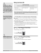
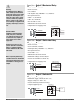
Figure 13a — 0 to 20 mA Process Input
(all model numbers)
• Input impedance 100 Ω, dc only.
• Controller does not supply power for the current loop.
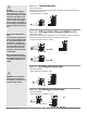
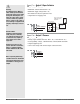
Figure 13b — Output 1 Mechanical Relay
SD_ _ - _ J _ _ - _ _ _ _
• Form A contact
• 2 A, resistive
• 125 VA pilot duty, 120/240VÅ (ac), inductive
• See Quencharc note.
• 240VÅ (ac) maximum.
• 30VÎ (dc) maximum.
• For use with ac or dc.
• Minimum load current 10 mA
• Output does not supply power.
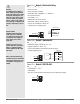
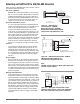
Figure 13c — Output 1 Solid-state Relay
SD_ _ - _ K _ _ - _ _ _ _
• Form A contact
• 0.5 A maximum, resistive
• 20 VA pilot duty, 120/240VÅ (ac), inductive
• See Quencharc note.
• 24 to 240VÅ (ac).
• Minimum load current 10 mA
• Maximum leakage current 100 µA
• Not for use with direct current (dc).
• Output does not supply power.
Internal Circuitry
COM.
N.O.
Solid-state Relay
5
6
Solid-state Switch
4
56
normally open 6
common 5
Internal Circuitry
COM.
N.O.
Mechanical Relay
5
6
4
56
normally open 6
common 5
8
9
10
11
5
6
7
8
11
+
+
+
-
-
-
Transmitter
Power
Supply
Two Wire Transmitter Wiring
4
8
9
10
11
5
6
7
8
11
6
8
9
10 11
8
11
+
-
ç
WARNING: Process input may
not have sensor break protec-
tion. Outputs can remain full on.
Check your input settings.
ç
Warning:
Use National Electric (NEC) or
other country-specific standard
wiring and safety practices when
wiring and connecting this con-
troller to a power source and to
electrical sensors or peripheral
devices. Failure to do so may re-
sult in damage to equipment and
property, and/or injury or loss of
life.
Quencharc Note:
Switching pilot pilot duty induc-
tive loads (relay coils, sole-
noids, etc.) with the mechanical
relay or solid-state relay output
options requires use of an R.C.
suppressor.
Watlow carries the R.C. sup-
pressor Quencharc brand name,
which is a trademark of ITW
Paktron. Watlow Part No. 0804-
0147-0000.
Spring clamp wiring connector
note:
To insert the wire, push the wire
into the desired connection num-
ber, and it should automatically
lock into place. To remove the
wire, press and hold the orange
release tab with a small screw-
driver. Pull the wire out of the
connection. Solid or tinned wire
recommended.
Note: To prevent ground loops,
isolation needs to be maintained
from input to output when using
switched DC or analog process
outputs.