
User`s manual


Watlow Series SD ■ 11 ■ Chapter 2 Install and Wire
Ó
Warning:
Use National Electric (NEC) or
other country-specific standard
wiring and safety practices when
wiring and connecting this con-
troller to a power source and to
electrical sensors or peripheral
devices. Failure to do so may re-
sult in damage to equipment and
property, and/or injury or loss of
life.
Note: To prevent ground loops,
isolation needs to be maintained
from input to output when using
switched DC or analog process
outputs.
Ó
WARNING: If high voltage is ap-
plied to a low-voltage controller,
irreversible damage will occur.
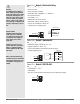
Wiring the Series SD
The model number for each output option appears with its wiring dia-
gram. Check the label on the controller and compare your model number to
those shown here and to the model number breakdown in the Appendix of
this manual.
The connectors on the back of the Series SD are different for different
model numbers. Where two different combinations of connectors may appear,
we show both in the diagrams.
All outputs, including normally open and normally closed contacts, are
referenced to a de-energized state (the controller has power removed).
All wiring and fusing must conform to the National Electric Code and to
any locally applicable codes as well.
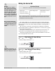
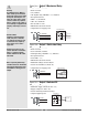
Figure 11a — High Voltage AC Power Wiring
SD_ _ - H _ _ _ - _ _ _ _ High
• Nominal voltage: 100 to 240VÅ (ac)
Figure 11b — Low Voltage AC Power Wiring
SD_ _ - L _ _ _ - _ _ _ _ Low
• Nominal voltage: 24‡ (ac/dc)
• Class 2 power source required for agency compliance
1
2
+
-
1
2
3
1
2
L2
L1
1
2
3
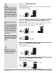
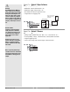
Isolation Blocks
There are no electrical connections between these blocks.
Relay outputs (mechanical and solid-state) provide isolation through their
relay contacts. Each relay output is isolated from the blocks above and is
isolated from other relay outputs.
Sensor Input
Switched DC Outputs
Analog Process Outputs
Power Supply Input EIA/TIA-485 Communi-
cations Input