
User`s manual


ç
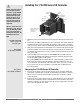
Caution: Follow the installa-
tion procedure exactly to
guarantee a proper IP65/NE-
MA 4X seal. Make sure the
gasket between the panel
and the rim of the case is
not twisted and is seated
properly. Failure to do so
could result in damage to
equipment.
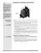
Note: Be careful not to over-
tighten the screws. This may
cause the mounting bracket
to fail. If the front bezel is
touching the front panel, the
mounting bracket is too
tight.
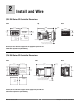
Installing the 1/8 DIN Series SD Controller
1. Make the panel cutout using the mounting template dimensions in this chap-
ter.
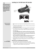
2. Check that the rubber gasket lies in its slot at the back of the bezel. Insert the
controller into the panel cutout. Slide the retention collar over the controller,
with the locating holes facing the back of the controller.
3. Slide the mounting bracket over the back of the controller with the screw tips
pointed toward the panel, aligning with the locating holes in the retention col-
lar. Push it gently but firmly over the controller until the hooks snap into the
slots at the front.
4. If the installation does not require an IP65/NEMA 4X seal, tighten the four
screws with the Phillips screwdriver just enough to eliminate the spacing be-
tween the rubber gasket and the panel.
For an IP65/NEMA 4X seal, tighten the four screws until the gap between the
bezel and panel surface is 0.5 mm (0.020 in) maximum. Make sure that you
cannot move the controller back and forth in the cutout. If you can, you do not
have a proper seal. Do not over-tighten. Over-tightening could damage the the
mounting bracket.
Removing the 1/8 DIN Series SD Controller
1. Remove all the wiring connectors from the back of the controller. Using the
Phillips screwdriver, unscrew the four screws on the mounting bracket until
they disengage from the retention collar.
2. Squeeze the release tabs on the long sides of the mounting bracket and slide
the mounting bracket off the back of the controller. Remove the retention col-
lar and push the controller out of the panel cutout. Be ready to support the
controller as it comes through the front panel.
Gasket
Bezel
Panel
Retention
Collar
Mounting
Bracket
Hook
Slot
Release
Ta b
Locating Hole
Arrows indicate the
direction of pull to
remove the
connectors.
Case
Watlow Series SD ■ 8 ■ Chapter 2 Install and Wire
Installing and mounting
requires access to the
back of the panel.
Tools required:
one #2 Phillips screwdriver.
Tools required:
one #2 Phillips screwdriver.