
- Watlow EZ-ZONE PM Integrated Controller User Manual


Watlow EZ-ZONE
®
PM Integrated Controller • 69 • Appendix
Specifications
Line Voltage/Power
• 85 to 264VÅ (ac), 47 to 63 Hz
• 12 to 40VÎ (dc); 20 to 28VÅ (ac), 47 to 63 Hz
• 10VA maximum power consumption
• Data retention upon power failure via nonvolatile memory
• Compliant with Semi F47-0200, Figure R1-1 voltage sag require-
ments @ 24Å (ac) or higher
Environment
• -18 to 65°C (0 to 149°F) operating temperature
• -40 to 85°C (-40 to 185°F) storage temperature
• 0 to 90 percent RH, non-condensing
Accuracy
• Calibration accuracy and sensor conformity: ±0.1 percent of ac-
curacy span, ±1°C at the calibrated ambient temperature and
rated line voltage
• Types R, S, B; 0.2 percent
• Type T below -50°C (58°F); 0.2 percent
• Calibration ambient temperature @ 25°C, ±3°C (77°F, ±5°F)
• Accuracy span: 540°C (1,000°F) minimum
• Temperature stability: ±0.1°C/°C (±0.1°F/°F) rise in ambient
maximum
• Process Output: ±15 mV using 0 to 10 VÎ (dc), resolution @ 3
mV and ±30 μA using 0 to 20 mA, resolution @ 6 μA
Agency Approvals
• UL
®
Listed to UL 61010-1 File E185611.
• UL Reviewed to CSA C22.2 No. 61010-1-04.
• UL 50 Type 4X, NEMA 4X indoor locations, IP66 front panel seal.
• FM Class 3545 File 3029084 temperature limit switches.
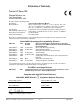
• CE – See Declaration of Conformity. RoHS and W.E.E.E. compliant.
• ODVA – EtherNet/IP™ Compliance.
•
UL
®
Listed to ANSI/ISA 12.12.01-2001 File E184390.
• UL reviewed to CSA C22.2 No. 213-1987.
• This equipment is suitable for use in Class I, Division 2, Groups A,
B, C and D or Non-Hazardous locations only. Temperature Code
T4A.
• WARNING – EXPLOSION HAZARD. Substitution of component
may impair suitability for Class I, Division 2.
• WARNING – EXPLOSION HAZARD. Do not disconnect equipment
unless power has been switched off or the area is known to be non-
hazardous.
Controller
• Microprocessor-based, user-selectable control modes
• PID module: Single universal input, 2 outputs
• Limit module: Single universal input, 2 outputs
• 2 total additional digital input/outputs shared between PID and
limit functions
• Control sampling rates: input 10 Hz, outputs 10 Hz
Serial Communications
• Isolated communications EIA-485, Standard Bus: all models;
EIA-232/485, Modbus™ RTU and Ethernet IP/Modbus™ TCP
serial communications. Future options include DeviceNet™ and
Profibus™ DP
Wiring Termination, Touch-Safe Terminals
• Input, power and controller output terminals touch-safe remov-
able 3.30 to 0.0507mm² (12 to 30 AWG)
• Wire strip length 7.6 mm (0.30 in)
• Torque 0.8 Nm (7.0 lb.- in.)
Universal Input
• Thermocouple, grounded or ungrounded sensors
>20 MΩ input impedance
Maximum of 2K Ω source resistance
• RTD 2- or 3-wire, platinum, 100 and 1,000 Ω @ 0°C calibration
to DIN curve (0.00385 Ω/Ω/°C); lead resistance effect: 0.3°C/Ω
maximum
• Process, 0 to 20 mA @ 100 Ω, or 0 to 10VÎ (dc) and 0 to 50 mV @
20 kΩ input impedance; scalable
• Inverse scaling
Accuracy Range
Type J: 0 to 750°C or 32 to 1,383°F (±1.75°C)
Type K: -200 to 1,250°C or -328 to 2,282°F (±2.45°C)
Type T: -200 to 350°C or -328 to 662°F (±1.55°C)
Type E: -328 to 1,652°C or -200 to 900°F (±2.10°C)
Type N: 0 to 1,250°C or 32 to 2,282°F (±2.25°C)
Type C: 0 to 2,315°C or 32 to 4,199°F (±3.32°C)
Type D: 0 to 2,315°C or 32 to 4,199°F (±3.32°C)
Type F: 0 to 1,343°C or 32 to 2,450°F (±2.39°C)
Type R: 0 to 1,450°C or 32 to 2,642°F (±3.90°C)
Type S: 0 to 1,450°C or 32 to 2,642°F (±3.90°C)
Type B: 870 to 1,700°C or 1,598 to 3,092°F (±2.66°C)
RTD (DIN): -200 to 800°C or -328 to 1,472°F (±2.00°C)
Volts: 0 to 10 (±0.01V)
mA DC: 0 to 20 (±0.02 mA)
mV: 0 to 50 (±0.05 mV)
Potentiometer: 0 to 1,200 Ω (±1.0 Ω)
Functional Operating Range
Type J: -210 to 1,200°C or -346 to 2,192°F
Type K: -200 to 1,370°C or -328 to 2,500°F
Type T: -200 to 400°C or -328 to 750°F
Type E: -200 to 1,000°C or -328 to 1,832°F
Type N: -200 to 1,300°C or -328 to 2,372°F
Type C: 0 to 2,315°C or 32 to 4,200°F
Type D: 0 to 2,315°C or 32 to 4,200°F
Type F: 0 to 1,395°C or 32 to 2,543°F
Type R: -50 to 1,767°C or -58 to 3,214°F
Type S: -50 to 1,767°C or -58 to 3,214°F
Type B: 0 to 1,816°C or 32 to 3,300°F
RTD (DIN): -200 to 800°C or -328 to 1,472°F
Process: -1,999 to 9,999 units
Digital Input
• Update rate 10 Hz
• Dry contact or dc voltage
DC voltage
• Maximum input 36V at 3 mA
• Minimum high state 3V @ 0.25 mA
• Maximum low state 2V
Dry contact
• Minimum open resistance 10 kΩ
• Maximum closed resistance 50 Ω
• Maximum short circuit 13 mA
Digital Output
• Update rate 10 Hz
• Output voltage 24V
• Current limit, Output 5, 24 mA maximum; Output 6, 10 mA
maximum
Current Measurement
• Requires optional current transformer 16-0246
• Accepts 0 to 50 mA signal (user programmable range) 2 to 50A
usable
• Displayed operating range and resolution can be scaled and are
user programmable.
Output Hardware
• User selectable for heat-cool as on-off, P, PI, PD, PID, alarm ac-
tion or limit.
Switched DC
• Unregulated 22 to 32VÎ (dc) low side @ 30 mA outputs 1 and 3,
10 mA outputs 2 and 4
Open Collector
• Output sink 100 mA @ 30VÎ (dc) maximum