
- Watlow EZ-ZONE PM Integrated Controller User Manual

Watlow EZ-ZONE
®
PM Integrated Controller • 15 • Chapter 2 Install and Wire
Ó
Warning:
Use National Electric (NEC)
or other country-specific
standard wiring and safety
practices when wiring and
connecting this controller to
a power source and to elec-
trical sensors or peripheral
devices. Failure to do so may
result in damage to equip-
ment and property, and/or
injury or loss of life.
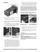
Note:
Maximum wire size termina-
tion and torque rating:
• 0.0507 to 3.30 mm
2
(30 to
12 AWG) single-wire termi-
nation or two 1.31 mm
2
(16
AWG)
• 0.8 Nm (7.0 lb.-in.) torque
Note:
Adjacent terminals may be
labeled differently, depend-
ing on the model number.
Note:
To prevent damage to the
controller, do not connect
wires to unused terminals.
Note:
Maintain electrical isolation
between analog input 1, digi-
tal input-outputs, switched
dc/open collector outputs and
process outputs to prevent
ground loops.
Note:
The control output common
terminal and the digital com-
mon terminal are referenced
to different voltages and
must remain isolated.
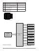
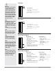
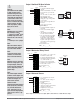
Input 2 Thermocouple
-
+
L3
K3
J3
L4
K4
T2
S2
R2
Slot B
• 20 Ω maximum source resistance
• >20 MΩ input impedance
• 3 microampere open-sensor detection
• Thermocouples are polarity sensitive. The negative lead (usually
red) must be connected to S2.
• To reduce errors, the extension wire for thermocouples must be
of the same alloy as the thermocouple.
PM6 _ _ _ _-_ (R or L) _ _ A _ _
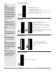
Input 2 RTD
2-wire
L3
K3
J3
L4
K4
T2
S2
R2
S1
S3
Slot B
3-wire
L3
K3
J3
L4
K4
T2
S2
R2
S1
S2
S3
Slot B
• platinum, 100 and 1,000 Ω @ 0°C
• calibration to DIN curve (0.00385 Ω/Ω/°C)
• 20 Ω total lead resistance
• RTD excitation current of 0.09 mA typical. Each
ohm of lead resistance may affect the reading by
0.03°C.
• For 3-wire RTDs, the S1 lead (usually white) must
be connected to R2.
• For best accuracy use a 3-wire RTD to compensate
for lead-length resistance. All three lead wires must
have the same resistance.
PM6 _ _ _ _-_ (R or L) _ _ A _ _
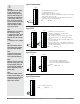
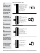
Input 2 Process
-
+
L3
K3
J3
L4
K4
T2
S2
R2
volts
Slot B
-
+
L3
K3
J3
L4
K4
T2
S2
R2
amperes
Slot B
• 0 to 20 mA @ 100 Ω input impedance
• 0 to 10VÎ (dc) @ 20 kΩ input impedance
• 0 to 50 mVÎ (dc) @ 20 kΩ input impedance
• scalable
PM6 _ _ _ _-_ (R, T or L) _ _ A _ _
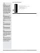
Input 2 Potentiometer
L3
K3
J3
L4
K4
T2
S2
R2
Slot B
CW
CCW
• Use a 1 kΩ potentiometer.
PM6 _ _ _ _-_ (R or L) _ _ A _ _