® EZ-ZONE PM User’s Manual Integrated Controller Models TOTAL CUST CUS TOMER SATISF TISFA ACTI CTIO ON 3 Year Warranty ISO 9001 Registered Company Winona, Minnesota USA 1241 Bundy Boulevard., Winona, Minnesota USA 55987 Phone: +1 (507) 454-5300, Fax: +1 (507) 452-4507 http://www.watlow.com 0600-0059-0000 Rev. C March 2008 Made in the U.S.A. $15.
Safety Information • Complete model number We use note, caution and warning symbols throughout this book to draw your attention to important operational and safety information. • All configuration information A “NOTE” marks a short message to alert you to an important detail. A “CAUTION” safety alert appears with information that is important for protecting your equipment and performance. Be especially careful to read and follow all cautions that apply to your application.
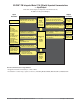
TC Table of Contents Chapter 1: Overview . . . . . . . . . . . . . . . . . . . . . . . . . . . . . . . . . . . . .2 Standard Features and Benefits . . . . . . . . . . . . . . . . . . . . . . . . . . . . . . . 2 Chapter 2: Install and Wire . . . . . . . . . . . . . . . . . . . . . . . . . . . . . . . . .8 Chapter 3: Keys and Displays . . . . . . . . . . . . . . . . . . . . . . . . . . . . . . 24 Attention Codes . . . . . . . . . . . . . . . . . . . . . . . . . . . . . . . . . . . . . . . . . .
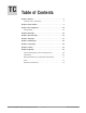
1 Chapter 1: Overview ® The EZ-ZONE PM takes the pain out of solving your thermal loop requirements. Watlow’s EZ-ZONE ® PM controllers offer options to reduce system complexity and the cost of controlloop ownership. You can order the EZ-ZONE ® PM as a PID controller or an over-under limit controller, or you can combine both functions in the PM Integrated Limit Controller.
A Conceptual View of the PM The flexibility of the PM’s software and hardware allows a large range of configurations. Acquiring a better understanding of the controller’s overall functionality and capabilities while at the same time planning out how the controller can be used will deliver maximum effectiveness in your application. It is useful to think of the controller in three parts: inputs; procedures; and outputs.
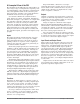
EZ-ZONE® PM Integrated Model 1/16 DIN with a Current Transformer — Input/Output (no communications options 2 to 3) Universal Sensor Input, Configuration Communications, Red/Green 7-Segment Display Output Functions Input Functions input sensor none, idle set point, alarm reset, tune, silence alarm, manual/auto mode, control outputs off, lock keypad, force alarm, TRU-TUNE+® disable loop & alarms off, profile disable, profile hold/resume, profile start, profile start/stop, restore user settings Network remote us
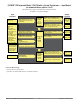
EZ-ZONE® PM Integrated Model 1/16 DIN with Remote Set Point — Input/Output (no communications options 2 to 3) Universal Sensor Input, Configuration Communications, Red/Green 7-Segment Display Output Functions Input Functions input sensor none, idle set point, alarm reset, tune, silence alarm, manual/auto mode, control outputs off, local-remote, lock keypad, force alarm, TRU-TUNE+® disable loop & alarms off, profile disable, profile hold/resume, profile start, profile start/stop, restore user settings Network
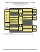
EZ-ZONE® PM Integrated Model 1/16 DIN with a Limit — Input/Output (no communications options 2 to 3) Universal Sensor Input, Configuration Communications, Red/Green 7-Segment Display Output Functions Input Functions input sensor none, limit reset, idle set point, tune, alarm reset, silence alarm, manual/auto mode, control outputs off, lock keypad, force alarm, TRU-TUNE+® disable loop & alarms off, profile disable, profile hold/resume, profile start, profile start/stop, restore user settings Network remote use
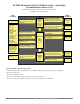
EZ-ZONE® PM Integrated Model 1/16 DIN with Expanded Communications — Input/Output Universal Sensor Input, Configuration Communications, Red/Green 7-Segment Display Output Functions Input Functions input sensor none, idle set point, tune, alarm reset, silence alarm, manual/auto mode, control outputs off, lock keypad, force alarm, TRU-TUNE+® disable loop & alarms off, profile disable, profile hold/resume, profile start, profile start/stop, restore user settings Network remote user interface, personal computer,
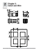
2 Chapter 2: Install and Wire Dimensions 15.8 mm (0.62 in) 101.6 mm (4.00 in) 53.3 mm (2.10 in) 53.3 mm (2.10 in) Side Front 51.2 mm (2.02 in) L1 L3 K1 K3 99 J1 J3 CF L2 K2 98 L4 CD K4 CE T1 T2 B5 S1 S2 D6 R1 R2 D5 Top Back 45.2 mm (1.78 in) Recommended panel spacing 45.2 mm (1.78 in) panel thickness 1.53 to 9.52 mm (0.060 to 0.375) 21.6 mm (0.85 in) 21.6 mm (0.
Installation The tabs on each side of the mounting collar have teeth that latch into the ridges on the sides of the controller. Each tooth is staggered at a different depth from the front so that only one of the tabs, on each side, is locked onto the ridges at a time. panel retention collar bezel gasket Note: There is a graduated measurement difference between the upper and lower half of the display to the panel.
Returning the Controller to its Case 1. Ensure that the orientation of the controller is correct and slide it back into the housing. Note: The controller is keyed so if it feels that it will not slide back in do not force it. Check the orientation again and reinsert after correcting. 2. Using your thumbs push on either side of the controller until both latches click. Chemical Compatibility This product is compatible with acids, weak alkalis, alcohols, gamma radiation and ultraviolet radiation.
Slot A Slot B Output 1 2 3 X1 W1 Y1 Terminal Function Configuration common (Any switched dc output can use this common.
Slot C Terminal Function Configuration 98 99 power input: ac or dc+ power input: ac or dc- all CC CA CB Standard Bus or Modbus RTU EIA-485 common Standard Bus or Modbus RTU EIA-485 T-/RStandard Bus or Modbus RTU EIA-485 T+/R+ Standard Bus or Modbus PM6 _ _ _ _-1 _ _ _ A _ _ CF CD CE Standard Bus EIA-485 common Standard Bus EIA-485 T-/RStandard Bus EIA-485 T+/R+ PM6 _ _ _ _-(A, 2 or 3) _ _ _ A _ _ B5 D6 D5 digital input-output common digital input or output 6 digital input or output 5 PM6 _ 2 _
Ó Low Power Slot C 98 Warning: Use National Electric (NEC) or other country-specific standard wiring and safety practices when wiring and connecting this controller to a power source and to electrical sensors or peripheral devices. Failure to do so may result in damage to equipment and property, and/or injury or loss of life.
Ó Input 1 Thermocouple Slot A L1 Warning: Use National Electric (NEC) or other country-specific standard wiring and safety practices when wiring and connecting this controller to a power source and to electrical sensors or peripheral devices. Failure to do so may result in damage to equipment and property, and/or injury or loss of life. • • • • 20 Ω maximum source resistance >20 MΩ input impedance 3 microampere open-sensor detection Thermocouples are polarity sensitive.
Ó Input 2 Thermocouple Slot B L3 Warning: Use National Electric (NEC) or other country-specific standard wiring and safety practices when wiring and connecting this controller to a power source and to electrical sensors or peripheral devices. Failure to do so may result in damage to equipment and property, and/or injury or loss of life. • • • • 20 Ω maximum source resistance >20 MΩ input impedance 3 microampere open-sensor detection Thermocouples are polarity sensitive.
Ó Warning: Use National Electric (NEC) or other country-specific standard wiring and safety practices when wiring and connecting this controller to a power source and to electrical sensors or peripheral devices. Failure to do so may result in damage to equipment and property, and/or injury or loss of life. Input 2 Current Transformer Slot B L3 K3 J3 L4 K4 T2 • Input range is 0 to 50 mA.
Switched DC • 30 mA dc maximum supply current • short circuit limited to <50 mA • 22 to 32VÎ (dc) open circuit voltage • Use dc- and dc+ to drive external solid-state relay.
Ó Warning: Use National Electric (NEC) or other country-specific standard wiring and safety practices when wiring and connecting this controller to a power source and to electrical sensors or peripheral devices. Failure to do so may result in damage to equipment and property, and/or injury or loss of life. Output 1 Solid-state Relay, Form A Slot A normally open common • 0.
Ó Warning: Use National Electric (NEC) or other country-specific standard wiring and safety practices when wiring and connecting this controller to a power source and to electrical sensors or peripheral devices. Failure to do so may result in damage to equipment and property, and/or injury or loss of life. Output 2 Solid-state Relay, Form A Slot A • 0.
Ó Warning: Use National Electric (NEC) or other country-specific standard wiring and safety practices when wiring and connecting this controller to a power source and to electrical sensors or peripheral devices. Failure to do so may result in damage to equipment and property, and/or injury or loss of life. Note: Maximum wire size termination and torque rating: • 0.0507 to 3.30 mm2 (30 to 12 AWG) single-wire termination or two 1.31 mm2 (16 AWG) • 0.8 Nm (7.0 lb.-in.
Ó Warning: Use National Electric (NEC) or other country-specific standard wiring and safety practices when wiring and connecting this controller to a power source and to electrical sensors or peripheral devices. Failure to do so may result in damage to equipment and property, and/or injury or loss of life. Output 4 Solid-state Relay, Form A Slot B L3 K3 J3 normally open common L4 K4 T2 S2 R2 • 0.
Ó Standard Bus EIA-485 Communications • Wire T-/R- to the A terminal of the EIA-485 port. • Wire T+/R+ to the B terminal of the EIA-485 port. • Wire common to the common terminal of the EIA-485 port. • Do not route network wires with power wires. Connect network wires in daisy-chain fashion when connecting multiple devices in a network.
Ó Warning: Use National Electric (NEC) or other country-specific standard wiring and safety practices when wiring and connecting this controller to a power source and to electrical sensors or peripheral devices. Failure to do so may result in damage to equipment and property, and/or injury or loss of life. Note: Maximum wire size termination and torque rating: • 0.0507 to 3.30 mm2 (30 to 12 AWG) single-wire termination or two 1.31 mm2 (16 AWG) • 0.8 Nm (7.0 lb.-in.
3 Chapter 3: Keys and Displays Temperature Units Indicator Lights: Upper Display: In the Home Page, displays the process value, otherwise displays the value of the parameter in the lower display. WATLOW Indicates whether the temperature is displayed in Fahrenheit or Celsius. EZ-ZONE® Zone Display: Output Activity: Indicates the controller zone that the remote user interface (RUI) is currently communicating with. Number lights indicate activity of outputs 1 through 5.
® Navigating the EZ-ZONE PM Integrated Controller WATLOW EZ-ZONE ® [``Ai] [`Set] WATLOW EZ-ZONE ® [``70] [``72] Home Page from anywhere: Press the Infinity Key ˆ for two seconds to return to the Home Page. WATLOW EZ-ZONE ® [``70] [``72] WATLOW EZ-ZONE ® [``Ai] [oper] Operations Page from Home Page: Press both the Up ¿ and Down ¯ keys for three seconds.
4 Chapter 4: Home Page Default Home Page Parameters The Home Page is a customized list of as many as 20 parameters that can be configured and changed in the Custom Menu [CUSt] (Factory Page). The default list of nine parameters below includes the Active Process Value (value in upper display) and Active Set Point (value in lower display). The Attention [Attn] parameter appears only if there is an active message.
Display Parameter Name Description Setting Range [Attn] Attention An active message will cause the display to toggle between the normal settings and the active message in the upper display and [Attn] in the lower display. Your response will depend on the message and the controller settings. Some messages, such as Ramping and Tuning, indicate that a process is underway. If the message was generated by a latched alarm or limit condition, the message can be cleared when the condition no longer exists.
5 Chapter 5: Operations Page • Press the Advance Key ‰ to move through the parameters of the menu or submenu. • Press the Infinity Key ˆ to move backwards through the levels: parameter to submenu; submenu to menu; menu to Home Page. • Press and hold the Infinity Key ˆ for two seconds to return to the Home Page. To go to the Operations Page from the Home Page, press both the Up ¿ and Down ¯ keys for three seconds. [``Ai] will appear in the upper display and [oPEr] will appear in the lower display.
Display Parameter name Description [``Ai] [oPEr] Analog Input Menu [```1] [``Ai] Analog Input 1 or Settings Range [```2] [``Ai] Analog Input 2 Default Appears If (input 2 appears if PM6 _ _ _ _-_ [R, T or L] _ _ A _ _) [`Ain] [ Ain] Analog Input (1 or 2) Process Value View the process value. -1,999.000 to 9,999.000°F or units -1,128.000 to 5,537.000°C always [`i;Er] [ i.Er] Analog Input (1 or 2) Error Status View the cause of the most recent error.
Display Parameter name Description Settings Range Default Appears If [Loop] [oPEr] Loop Menu [`r;En] [ r;En] Loop Remote Enable Switch control to the remote set point. [``no] No [`YES] Yes No PM6 _ _ _ _-_ (R )__AAA [`r;ty] [ r.ty] Loop Remote Set Point Type Select how the remote set point will be determined. [AUto] Auto (closed loop) [MAn] Manual (open loop) Auto Remote Enable is set to Yes. [`C;M] [ C.M] Loop Control Mode Select the method that the controller will use to control.
Display Parameter name Description Settings Range Default Appears If [``dB] [ db] Loop Dead Band Set the offset to the proportional band. With a negative value, both heating and cooling outputs are active when the process value is near the set point. A positive value keeps heating and cooling outputs from fighting each other. -1,000.0 to 1,000.0°F or units -556 to 556°C 0.0 Heat Algorithm and Cool Algorithm (Setup Page) are set to PID or On-Off. [`o;SP] [ o.
Display Parameter name Description Settings Range [P;Str] {P.Str] Profile Status Profile Start Select a step or profile to load. 1 to 40 [P;ACr] {P.ACr] Profile Status Profile Action Request Select what action to apply to the currently loaded profile. [nonE] [ProF] [PAUS] [rESU] [`End] [StEP] [`StP] [ StP] Profile Status Active Step View the currently running step. [S;typ] [S.
6 Chapter 6: Setup Page Home Page Setup Page Parameters [~~p~]ň [~`A1]ň [~~~1]ň È Ç [~~Sp]<>Æ [~set]‰Æ [~~AI]‰Æ [~sen]‰Æ[~lin]‰Æ[`Rt;l]‰Æ[`s;lo]‰Æ[`s;hi]‰Æ[`r;lo]‰Æ[`r;hi]‰Æ[`P;EE]‰Æ[`P;EL]‰Æ[`FiL]‰Æ[`i;Er]‰Æ[`dEC]‰Æ [`S;bA]‰ Input 1 Submenu <Ç È> Hold both keys Analog Input for 6 seconds.
To go to the Setup Page from the Home Page, press both the Up ¿ and Down ¯ keys for six seconds. [``Ai] will appear in the upper display and [`Set] will appear in the lower display. • Press the Up ¿ or Down ¯ key to move through the menus. • Press the Advance Key ‰ to move to a submenu. • Press the Up ¿ or Down ¯ key to move through the submenus. • Press the Advance Key ‰ to move through the parameters of the menu or submenu.
Display Parameter Name Description [`P;EL] [ P.EL] Input (1 or 2) Process Error Low If the process value drops below this value, it will trigger an input error. -100.0 to 1,000.0 0.0 Sensor Type is set to Millivolts, Volts, Milliamps or Potentiometer 1 kΩ, and Error Enable is set to Low. [`FiL] [ FiL] Input (1 or 2) Filter Time Filtering smooths out the process signal to both the display and the input. Increase the time to increase filtering. 0.0 to 60.0 seconds 0.5 always [`i;Er] [ i.
Display Parameter Name Description [`leu] [ LEu] Digital Input (5 or 6) Level Select what action will be interpreted as a true state. [high] High [Low] Low High Direction is set to Input Voltage or Input Dry Contact. [``Fn] [ Fn] Digital Input (5 or 6) Function Select the function that will be triggered by a true state. Functions respond to a level state change or an edge level change.
Display Parameter Name Description Settings Range Default Appears If sp;ll Limit [SP.LL] Set Point Limit Low Clamp the operational limit low maximum setting to this value. -1999.000 - 9999.000 -1999.000 always [`L;it] [ L.it] [``no] No [`YES] Yes No always Limit Integrate In a limit state the controller will turn off the outputs, terminate an active profile and freeze PID and TRU-TUNE+® calculations. [Loop] [`Set] Loop Menu [`h;Ag] [ h.Ag] Loop Heat Algorithm Set the heat control method.
Display Parameter Name Description Settings Range Default Appears If [FAiL] [FAiL] Loop Input Error Failure Select what the controller outputs will do when an input error switches control to manual mode.
Display Parameter Name Description [otpt] [`Set] Output Menu [```1] [otpt] Output 1 [```2] [otPt] Output 2 Settings [```3] [otpt] Output 3 Range [```4] [otpt] Output 4 Default Appears If (check model number for output information) [`o;ty] [ o.ty] Output (1 or 3) Type Select whether the process output will operate in volts or milliamps. [uoLt] Volts [`MA] Milliamps Volts [``Fn] [ Fn] Output (1 or 3) Function Select what function will drive this output.
Display Parameter Name Description [``Fn] [ Fn] Output (1 to 4) Function Select what function will drive this output. Heat [`oFF] Off Alarm [hEAt] Heat Off (outputs 3 [CooL] Cool & 4) [ALM] Alarm [`Ent] Event [LiM] Limit (outputs 3 & 4) a time-proportioned output (solid-state relay, switched dc or mechanical relay) [``Fi] [ Fi] Output (1 to 4) Function Instance Select which source instance will drive the output.
Display Parameter Name Description Settings Range Default Appears If [`A;hy] [ A.hy] Alarm (1 to 4) Hysteresis Set the hysteresis for an alarm. This determines how far into the safe region the process value needs to move before the alarm can be cleared. 0.001 to 9,999.000°F or units 0.001 to 5,555.000°C 1.0°F or units 1.0°C always [`A;Lg] [ A.Lg] Alarm (1 to 4) Logic Select what the output condition will be during the alarm state.
Display [`C;Si] [ C.Si] Parameter Name Description Settings Current Source Output Instance Select which output instance the current transformer will monitor. Range Default Appears If 1 to 6 1 (if not process) 2 (otherwise) always High always [`FUn] [`Set] Function Key Menu [`Leu] [ LEv] Function Key Level Select what state the Function Key will be in at startup. Pressing the Function Key will toggle the selected action.
Display Parameter Name Description [P;typ] [P.tyP] Global Profile Type Set the profile startup to be based on a set point or a process value. [StPt] Set Point [`Pro] Process Set Point the controller includes profiling (PM6 R _ _ _-_ _ _ _ A _ _). [`GSE] [ gSE] Global Guaranteed Soak Enable Enables the guaranteed soak deviation function in profiles. [`oFF] Off [``on] On Off the controller includes profiling (PM6 R _ _ _-_ _ _ _ A _ _).
Display Parameter Name Description Settings Range Default Appears If [iP;F3] [ip.F3] Communications 2 IP Fixed Address Part 3 Set the IP address of this controller. Each device on the network must have a unique address. 0 to 255 1 IP Address Mode is set to Fixed [iP;F4] [ip.F4] Communications 2 IP Fixed Address Part 4 Set the IP address of this controller. Each device on the network must have a unique address. 0 to 255 1 IP Address Mode is set to Fixed [iP;S1] [ip.
7 Chapter 7: Profiling Page Navigating the Profiling Page Profiling Page Home Page [~~p~] ˆ [~~p1] ˆ [~~Sp]‰ [FiLe]‰ Hold key for 3 seconds.
The Profiling Page allows you to enter your ramp and soak profile information. How to Start a Profile To go to the Profiling Page from the Home Page, press the Advance Key ‰ for three seconds, until [ProF] appears in the lower display and the profile number appears in the upper display. Press the Up ¿ or Down ¯ key to change to another profile. • Press the Advance Key ‰ to move to the selected profile's first step. • Press the Up ¿ or Down ¯ keys to move through the steps.
Display Parameter name Description Settings Range (Integer values for Modbus in parentheses.) Default Appears If [hoUr] [hoUr] Step Type Parameters Hours Select the hours (plus Minutes and Seconds) for a timed step. 0 to 99 0 Step Type is set to Time or Soak. [Min] [Min] Step Type Parameters Minutes Select the minutes (plus Hours and Seconds) for a timed step. 0 to 59 0 Step Type is set to Time or Soak.
Display Step Type Description Parameters in Step Type Profiling parameters appear if the controller includes profiling (PM6 R _ _ _-_ _ _ _ A _ _). [``ti] [ ti] Step Types Time A Time Step controls at the Target Set Point and maintains two event output states for the designated time.
8 Chapter 8: Factory Page • Press the Infinity Key ˆ to return to the Home Page. To go to the Factory Page from the Home Page, press and hold both the Advance ‰ and Infinity ˆ keys for six seconds. • Press the Advance Key ‰ to move through the parameter prompts. • Press the Up ¿ or Down ¯ keys to change the parameter value. Note: Avoid continuous writes within loops. Excessive writes to EEPROM will cause premature EEPROM failure. The EEPROM is rated for 1,000,000 writes.
Display Parameter Name Description [CUSt] [FCty] Custom Menu [`PAr] [ PAr] [```1] [CUSt] Custom 1 Settings The Parameter 1 value will appear in the upper display of the Home Page. It cannot be changed with the Up and Down Keys in the Home Page. The Parameter 2 value will appear in the lower display in the Home Page. It can be changed with the Up and Down Keys, if the parameter is a writable one. [`iid] [ iid] Custom Menu Instance Select which instance of the parameter will be selected.
Display Parameter Name Description Settings Range Default Appears If [rLoC] [rLoC] Lockout Menu Read Lockout Security Set the read security clearance level. The user can access the selected level and all lower levels. If the Set Lockout Security level is higher than the Read Lockout Security, the Read Lockout Security level takes priority.
Display Parameter Name Description Settings Range Default Appears If [iP;A3] [iP.A3] Diagnostics Menu IP Actual Address Part 3 Display the third part of this controller's IP address. 0 to 255 None the controller includes EtherNet/ IP (PM6 _ _ _ _3AA _ A _ _). [iP;A4] [iP.A4] Diagnostics Menu IP Actual Address Part 4 Display the fourth part of this controller's IP address. 0 to 255 None the controller includes EtherNet/ IP (PM6 _ _ _ _3AA _ A _ _). [C;LEd] [C.
9 Chapter 9: Features Saving and Restoring User Settings . . . . . . . . . . . . . . . . . . . . . . . . . . 54 Programming the Home Page . . . . . . . . . . . . . . . . . . . . . . . . . . . . . . 54 Tuning the PID Parameters . . . . . . . . . . . . . . . . . . . . . . . . . . . . . . . . 54 Manual Tuning . . . . . . . . . . . . . . . . . . . . . . . . . . . . . . . . . . . . . . . . . . . 55 Autotuning with TRU-TUNE+™ . . . . . . . . . . . . . . . . . . . . . . . . . . . . . . . 55 Inputs . . . . . . . .
Saving and Restoring User Settings Recording setup and operations parameter settings for future reference is very important. If you unintentionally change these, you will need to program the correct settings back into the controller to return the equipment to operational condition. After you program the controller and verify proper operation, use User Save Set [USr;S] (Factory Page, Diagnostics Menu) to save the settings into either of two files in a special section of memory.
Manual Tuning In some applications, the autotune process may not provide PID parameters for the process characteristics you desire. If that is the case, you may want to tune the controller manually. 1. Apply power to the controller and establish a set point typically used in your process. 2. Go to the Operations Page, Loop Menu, and set Heat Proportional Band [`h;Pb] and/or Cool Proportional Band [`C;Pb] to 5. Set Time Integral [``ti] to 0. Set Time Derivative [``td] to 0. 3.
3. Initiate an autotune. (See Autotuning in this chapter.) When autotuning is complete, the PID parameters should provide good control. As long as the loop is in the adaptive control mode, TRU-TUNE+ ® continuously tunes to provide the best possible PID control for the process. ç WARNING! During autotuning, the controller sets the output to 100 percent and attempts to drive the process variable toward the set point.
Set Electrical Offset to 0 and Electrical Slope to 1 to restore factory calibration. open-loop set point. High Limit of selected functional range Filter Time Constant Filtering smoothes an input signal by applying a first-order filter time constant to the signal. Filtering the displayed value makes it easier to monitor. Filtering the signal may improve the performance of PID control in a noisy or very dynamic system. Adjust the filter time interval with Filter Time [`FiL] (Setup Page, Analog Input Menu).
which allows its set point to be manipulated by an external source. A common application would use one ramping controller with a set-point retransmit output to ramp multiple controllers using the remote set point. Or you could use an analog output from a PLC to send set point values to an EZ-ZONE ® PM. The controller must have two process inputs to use the remote set point feature.
Output Scale Range High Range Low Scale Low Scale High Retransmit Source Set the range of the process output with Scale Low [`S;Lo] and Scale High [`S;hi]. Scale the retransmit source to the process output with Range Low [`r;Lo] and Range High [`r;hi]. When the retransmit source is at the Range Low value, the retransmit output will be at its Scale Low value. When the retransmit source is at the Range High value, the retransmit output will be at its Scale High value.
Actual Temperature Sensor Break 100% 2 minutes 0% Locks in Output Power Note: Input Error Failure Mode [faIl] does not function in onoff control mode. The output goes off. Time Input Error Latching [`i;Er] (Setup Page, Analog Input Menu) determines the controller’s response once a valid input signal returns to the controller. If latching is on, then the controller will continue to indicate an input error until the error is cleared. To clear a latched alarm, press the Advance Key ‰ then the Up Key ¿.
Set Point Reduced Overshoot Set Point Proportional Band Proportional Band x 2 Temperature In an application with one output assigned to heating and another assigned to cooling, each will have a separate proportional parameter. The heating parameter takes effect when the process temperature is lower than the set point, and the cooling parameter takes effect when the process temperature is higher than the set point.
When the dead band value is a negative value, both heating and cooling outputs are active when the temperature is near the set point. 50 percent output 3 ON, 3 OFF Cool Output Active Set Point Heat Output Active Temperature 66 percent output 6 ON, 3 OFF Negative Dead Band Time Adjust the dead band with Dead Band [``db] (Operations Page, Loop Menu). Note: Variable Time Base When output 1 is a universal process output, output 2 cannot use variable time base, fixed time base only.
value to the alarm low set point or subtracting the hysteresis value from the alarm high set point. View or change alarm hysteresis with Hysteresis [`A;hy] (Setup Page, Alarm Menu). Temperature Set Point degrees per minute High Side Alarm Range Temperature ramps to Set Point at a set rate Alarm High Set Point Alarm Hysteresis Temperature Time Alarms Alarms are activated when the output level, process value or temperature leaves a defined range.
Alarm Silencing Programming the EZ Key If alarm silencing is on the operator can disable the alarm output while the controller is in an alarm state. The process value or temperature has to enter the normal operating range beyond the hysteresis zone to activate the alarm output function again. An active message, such as an alarm message, will cause the display to toggle between the normal settings and the active message in the upper display and [Attn] in the lower display.
Using Lockout to Secure Settings If unintentional changes to parameter settings might raise safety concerns or lead to downtime, your can use the lockout feature to make them more secure. Each of the menus in the Factory Page and each of the pages, except the Factory Page, has a security level assigned to it. You can change the read and write access to these menus and pages by using the parameters in the Lockout Menu (Factory Page).
Chapter 10: Appendix Troubleshooting Alarms, Errors and Control Issues Indication Description Possible Cause(s) Alarm won’t clear or reset Alarm will not clear or reset • Alarm latching is active with keypad or digital input • Alarm set to incorrect output Alarm won’t occur Alarm will not activate output • Alarm silencing is active • Alarm blocking is active • Alarm is set to incorrect output Corrective Action • Reset alarm when process is within range or disable latching • Set output to correct ala
Indication Description Possible Cause(s) Corrective Action [Li;h1] Limit High [Li;h2] Sensor input above high limit • Temperature is greater than limit set • Check cause of over temperature set point point • Limit outputs latch and require reset • Clear limit • Incorrect alarm set point • Establish correct limit set point [LP;o1] Loop Open Error Open Loop Detect is active • Setting of Open Loop Detect Time and the process value did incorrect not deviate by a user-select- • Setting of Open Loop Detect
Indication Process doesn’t control to set point Description Process is unstable or never reaches set point Possible Cause(s) • Controller not tuned correctly • Perform autotune or manually tune system • Control mode is incorrectly set • Set control mode appropriately (Open vs Closed Loop) • Control set point is incorrect • Set control set point in appropriate control mode and check source of set point: remote, idle, profile, closed loop, open loop Temperature runway Process value continues to • Cont
Specifications • Process, 0 to 20 mA @ 100 Ω, or 0 to 10VÎ (dc) and 0 to 50 mV @ 20 kΩ input impedance; scalable • Inverse scaling Line Voltage/Power • • • • • 85 to 264VÅ (ac), 47 to 63 Hz 12 to 40VÎ (dc); 20 to 28VÅ (ac), 47 to 63 Hz 10VA maximum power consumption Data retention upon power failure via nonvolatile memory Compliant with Semi F47-0200, Figure R1-1 voltage sag requirements @ 24Å (ac) or higher Environment • -18 to 65°C (0 to 149°F) operating temperature • -40 to 85°C (-40 to 185°F) storag
Solid-State Relay • 0.
Ordering Information for Integrated Controller Models P M 6 __ __ __ __ Controller EZ-ZONE® Integrated Controller Models - __ __ __ __ A __ __ Universal Sensor Input, configuration communications TRU-TUNE+® Adaptive Tune, red-green 7-segment displays Package Size 6 1⁄16 DIN Primary Function C R S PID Controller Ramp and Soak Custom Firmware Power Supply, Digital Input/Output 1 2 3 4 100 to 240VÅ (ac) 100 to 240VÅ (ac) plus 2 digital i/o points 12 to 40VÎ (dc) and 20 to 28VÅ (ac) 12 to 40VÎ (dc) an
Index [`A;bL] Alarm Blocking 41, 64 [AC;LF] AC Line Frequency 42, 62 [AC;SP] Active Set Point 32 [Ad;M] Address Modbus 43 [`Ad;s] Address Standard Bus 43 [A;dSP] Alarm Display 41 [`A;hi] Alarm High Set Point 31, 63 [`A;hy] Alarm Hysteresis 41, 63 [``Ai] Analog Input Menu 29, 34 [`ain] Process Value 29 [`A;LA] Alarm Latching 41, 63 [AL;E1] [AL;E2] [AL;E3] [AL;E4] Alarm Error 1 to 4 24, 27 [`A;Lg] Alarm Logic 41 [AL;h1] [AL;h2] [AL;h3] [AL;h4] Alarm High 1 to 4 24, 27 [AL;L1] [AL;L2] [AL;L3] [AL;L4] Alarm Low
35, 39, 40 [``oP] Open Loop Set Point 31 [`o;tb] Output Time Base 35, 40 [otPt] Output Menu 39 [`o;ty] Output Type 39 [P;AC1] Profile Action Request 27 [P;AC1] Profile Action Request, Home Page 26 [P;ACr] Profile Action Request 32 [`PAr] Parameter 1 to 20 50 [`PAr] Parity 43 [PCoL] Protocol 43 [`P;EE] Process Error Enable 34 [`P;EL] Process Error Low 35 [``Pn] Part Number 51 [ProF] Profile 46 [P;St1] Profile Start 27 [P;St1] Profile Start, Home Page 26 [P;StA] Profile Status Menu 31 [P;Str] Profile Start 32
deviation alarms 63 Diagnostics Menu 51 Factory Page 49 Digital Input/Output Menu 29, 35 Operations Page 28 Setup Page 33 digital inputs 3 Digital Input Function 3, 42 digital input specifications 69 digital output specifications 69 dimensions 8, 70 Direction 35 Display 41 displays 24 Display Units 42 Down Key 24 duplex 58 E Electrical Gain 56 Electrical Input Offset 52 Electrical Input Slope 52 Electrical Measurement 52, 56 Electrical Output Offset 52 Electrical Output Slope 52 End 48 End Set Point Value
Output Menu 39 Setup Page 33 output power scaling 59 Output State 29 Output Type 39 P, Q P3T armor sealing system 2 Parameter 1 to 20 50 Parity 43 Part Number 51 percent units indicator light 24 process alarms 63 Process Error Enable 34 Process Error Low 35 Process Value 29 Process Value Active 29 Profile 46 Profile Action 26 Profile Action Request 32 Home Page 27 profile activity light 24 Profile Start 27, 32 Home Page 26 Profile Status Menu 31 Operations Page 28 Profile Type 43 Profiling Page 45, 50 prog
Declaration Declarationof of Conformity Conformity Series EZ Zone PM Watlow Winona, Inc. 1241 Bundy Blvd.
How to Reach Us Corporate Headquarters Europe Watlow Electric Manufacturing Company 12001 Lackland Road St. Louis, MO 63146 Sales: 1-800-WATLOW2 Manufacturing Support: 1-800-4WATLOW Email: info@watlow.com Website: www.watlow.com From outside the USA and Canada: Tel: +1 (314) 878-4600 Fax: +1 (314) 878-6814 Watlow France SARL Immeuble Somag 16, Rue Ampère 95307 Cergy-Pontoise CEDEX France Tel: + 33 (0)1 30 73 24 25 Fax: + 33 (0)1 30 73 28 75 Email: info@watlow.fr Website: www.watlow.