
User`s manual


Ó
Warning:
Use National Electric (NEC)
or other country-specific
standard wiring and safety
practices when wiring and
connecting this controller to
a power source and to elec-
trical sensors or peripheral
devices. Failure to do so may
result in damage to equip-
ment and property, and/or
injury or loss of life.
Watlow EZ-ZONE™ RUI/Gateway • 7 • Chapter 2 Install and Wire
T-/R-
T+/R+
com
98
99
CF
CD
CE
B5
D6
D5
power
T-/R-
T+/R+
common
98
99
CF
CD
CE
power
T-/R-
T+/R+
common
power
power
power
power
power
RUI and Gateway
EZ-ZONE ST
ST_ _ - A _ A _ -_ _ _ _
EZ-ZONE ST
ST_ _ - (B or F) _ A _ -_ _ _ _
98
99
CF
CD
CE
B5
D6
D5
E8
E7
E6
E5
E4
E3
E2
E1
Ethernet
Switch
Standard Bus
Network
EtherNet IP and/or Modbus TCP
Network
PC HMI
PLC
PLC
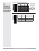
An RUI/Gateway allows for connectivity be-
tween dissimiliar networks.
Wiring a Serial EIA-485 Network
Do not route network wires with pow-
er wires. Connect network wires in
daisy-chain fashion when connecting
multiple devices in a network.
A termination resistor may be re-
quired. Place a 120 Ω resistor across
T+/R+ and T-/R- of the last controller
on a network.
Note: The RUI (remote user interface) without
a gateway installed can communicate using
Watlow's Standard Bus only.
Note: Do not route network wires with power
wires.
Note:
Excessive writes through the
gateway to other EZ-ZONE
family controllers may cause
premature EEPROM failure.
For more detail see the section
entitled “Saving Settings to
Nonvolatile Memory.”