
User`s manual


Watlow EZ-ZONE™ RUI/Gateway • 18 • Chapter 5 Networking with a Gateway
Using EtherNet/IP™
(Communications To/From a PLC):
There are two methods used to communicate to/from
a PLC, i.e., implicitly and explicitly. Once the gateway
instance is enabled for EtherNet/IP™ there are two
prompts that relate directly to these forms of com-
munication shown below. In the explanation below
note that it is the CIP offset that is being used not the
Modbus offset as shown in the graphic below.
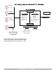
Use the graphic on the following page (RUI being
used as an Ethernet Gateway) in reference to the de-
scription that follows.
ost (CIP Offset) Used with explicit messages
where this prompt defines the instance off
set. The CIP offset is unique to each gateway
instance and should not overlap from one
gateway instance to another
As an Example:
When programming the message instruction in the
PLC the class, instance, and attribute needs to be de-
fined. To read the first instance of the process variable
in PM2 enter the following information in the message
instruction:
Class = 104
Instance = 5
Attribute = 1
Note that the instance is identified as instance 5 and
not 1. RUI prompt entry for gateway instance 1 fol-
lows:
[oSt] = 0
RUI prompt entry for gateway instance 2 follows:
[oSt] = 4
Likewise, to read the process value instance 2 of PM4
the following information would need to be entered in
the PLC message instruction:
Class = 104
Instance = 14
Attribute = 1
RUI prompt entry for gateway instance 3 follows:
[oSt] = 8
RUI prompt entry for gateway instance 4 follows:
[oSt] = 12
a;nb] (CIP Assembly Size) Used with implicit mess-
ages where this prompt defines the implicit
Assembly size. For any given RUI gateway
the input and output assembly size will never
be greater than 20 members. The user entry
ranges from 0 to 20 where all members can be
dedicated to one gateway instance or they can
be distributed any way the user sees fit across
the EZ-ZONE family controllers on the net-
work.
Using the graphic on the following page as an exam-
ple, if:
[Gtw] instance 1 has [a;nb] set to 5
[Gtw] instance 2 has [a;nb] set to 5
[Gtw] instance 3 has [a;nb] set to 5
[Gtw] instance 4 has [a;nb] set to 5
Note that the maximum assembly size of 20 has
not been exceeded.
Each of the four EZ-ZONE family controllers will
contain the first 5 members of the assembly. If it is
desired to modify the default members found in the
assembly or if you are simply looking for a better
understanding of the CIP assembly structure go to
the Watlow web site and download the EZ-ZONE PM
Communications User Manual: http://www.watlow.
com/literature/pti_search.cfm
Using Modbus TCP
(Communications To/From a Master):
When Modbus is enabled there are Modbus related
prompts that need to be addressed. They are:
1. Modbus TCP Enable [mb;e], turns Modbus on or
off.
2. Modbus TCP Word Order [m;hl], which allows
the user to swap the high and low order 16 bit val-
ues of a 32 bit member.
3. Modbus TCP Offset [m;of], which defines each of
the available Modbus registers for each gateway
instance.
As an example:
When using Modbus TCP notice that the Modbus
offset now applies. Lets assume the offsets are as
shown in the graphic on the following page and the
master wants to read the closed loop set point from
both Standard Bus address 1 and 4. Open up the PM
Communications then search for closed loop set point.
When found, you’ll notice that the Modbus register
that holds the closed loop set point value is 2160. To
read the set point from address 1 the appropriate ab-
solute Modbus address would be:
2160 + 400001 + Modbus offset (0) = 402161.
To read the closed loop set point from Standard
Bus address 4 the absolute address would be:
2160 + 400001 + Modbus offset (15000) = 417161.