INSTALLATION GUIDE AND OPERATING MANUAL ProSwitch-Xtreme ProSwitch-Xtreme Extreme Temperature Ethernet Switch CORPORATE HEADQUARTERS 5001 American Blvd., W. Suite 605 Bloomington, MN 55437 Phone: 800.441.5319 MANUFACTURING/CUSTOMER SERVICE th 945 37 Avenue, NW Rochester, MN 55901 Phone: 800.328.2275 www.watersnet.
Table of Contents 1.0 1.1 2.0 2.1 2.2 3.0 4.0 4.1 5.0 5.1 5.2 5.2.1 5.2.2 5.3 5.3.1 5.3.2 5.3.3 5.3.4 5.3.5 5.4 5.4.1 5.5 6.0 6.1 6.2 7.0 7.1 7.2 7.3 7.4 INTRODUCTION ......................................................................................................................2 PRODUCT DESCRIPTION ......................................................................................................2 FEATURES AND BENEFITS ..............................................................................
1.0 INTRODUCTION 1.1 Product Description The ProSwitch-Xtreme Extreme Temperature Ethernet Switches are designed to operate in abnormal temperature applications, and are suitable for use in harsh environments with inhospitable high/low temperatures.
Thermal design enables the ProSwitch-Xtreme to be used in uncontrolled temperature applications.
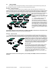
3.0 APPLICATIONS The ProSwitch-Xtreme is designed specifically for harsh temperature environments and brings future-proof fiber and widely used copper connectivity to out-of-the-way sites and the outdoors. Example 1. Traffic Control Sites In this example, a ProSwitch-Xtreme serves roadside real time traffic data collection and transmits it to a remote control station over fiber.
4.0 SPECIFICATIONS 4.1 Technical Specifications Ports Performance Fiber, and when an auto-negotiating port is operating at 100Mbps: When an RJ45 auto-negotiating port is operating at 10Mbps: Data Rate: 100Mbps Data Rate: 10Mbps Network Standards 100Mbps: Ethernet IEEE 802.3u, 100BASE-TX, 100BASE-FX 10Mbps: Ethernet IEEE 802.3, 10BASE-T Auto-sensing for speed: IEEE 802.
LED Indicators PWR: Steady ON when power applied SPEED (when LINK is ON): ON = 100Mbps; OFF = 10Mbps LINK/ACT: Steady ON for LINK with no traffic, blinking indicates port is transmitting/receiving. F/H (RJ45 ports only): ON = full-duplex, OFF = half-duplex MTBF (Bellcore method) Over 15 years MTBF Email: carolynl@watersnet.com Agency Approvals UL Listed (UL 1950), cUL, CE Emissions: meets FCC Part 15, Class B Warranty: Limited lifetime Made in USA 5.0 INSTALLATION 5.
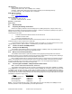
5.3.1 Connecting Twisted Pairs The following procedure describes how to connect a 10BASE-T or 100BASE-TX twisted pair segment to the RJ45 port. The procedure is the same for both unshielded and shielded twisted pair cables. 1. Using standard twisted pair media, insert either end of the cable with a RJ45 plug into the RJ45 connector of the port. Note that, even though the connector is shielded, either unshielded or shielded cables and wiring may be used. 2.
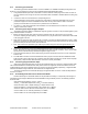
The following data has been collected from component manufacturer’s (HP’s and Siemens’) web sites and catalogs to provide guidance to network designers and installers. Fiber Port Module ProSwitchXtremexMSC ProSwitchXtremexSSC Speed, Std. Mode Std. km Wave- Cable X’mitr R’cvr Worst Worst* fdx length Size Output Sens. OPB, distance µm (hdx) PT , dB PR ,dB dB Nm Km, fdx Typical Typical* OPB, distance dB Km, fdx 100Mbps MultiFX mode 2 (0.4) 1300 62.5/125 -20 50/125 -23.5 -31 -31 9.0 5.5 2.5 2.
6.0 OPERATION 6.1 Dual-Speed Functionality and Switching The ProSwitch-Xtreme Ethernet switch provide six 10/100 RJ45 switched ports, and two 100Mbps fiber ports. The architecture supports a dual-speed switching environment, with two built-in full-duplex “future-proof” fiber ports. The six RJ45 copper ports equipped with auto-negotiation capability. The switched RJ45 ports are full/half duplex and auto-sensing for speed. (See section 2.2).
7.1 Before Calling for Assistance 1. If difficulty is encountered when installing or operating the unit, refer back to the Installation Section of the chapter of this manual. Also check to make sure that the various components of the network are interoperable. 2. Check the cables and connectors to ensure that they have been properly connected and the cables/wires have not been crimped or in some way impaired during installation.
connectors and this Installation Guide.) CAUTION: Do not pack the unit in Styrofoam "popcorn" type packing material. This material may cause electrostatic shock damage to the unit. Clearly mark the Return Material Authorization (RMA) number on the outside of the shipping container. Waters Network Systems is not responsible for your return shipping charges.