
Installation guide
12 QS3200 User’s Manual Page 6
2.2 100Base-FX Fiber Modules
Fiber modules are available in the following configurations:
PM-2SC Fiber module with two 100Base-FX multimode ports with SC connectors
PM-2ST Fiber module with two 100Base-FX multimode ports with ST connectors
PM-2MTRJ Fiber module with two 100Base-FX multimode ports with MTRJ connectors
PM-4SC Fiber module with four 100Base-FX multimode ports with SC connectors
PM-4ST Fiber module with four 100Base-FX multimode ports with ST connectors
PM-4MTRJ Fiber module with four 100Base-FX multimode ports with MTRJ connectors
Any of the modules listed above can be used to:
Connect the switch to the backbone of your network
Connect the switch to a classroom/workgroup hub or switch
Connect the switch to a server or workstation with a fiber NIC
2.3 10/100Base-TX Module (PM-8-UTP)
The 8-port 10/100Base-TX module provides eight 10/100Mbps switch ports that can be used to:
Connect the switch to the backbone of your network
Connect the switch to a classroom/workgroup hub or switch
Connect the switch to a server or workstation
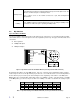
2.4 1000Base-SX, LX and TX Modules
The following choices are available for Gigabit speed:
PM-1G-UTP Copper Gigabit module with one 1000Base-TX port with RJ45 connector
PM-1G-MMSX Fiber Gigabit module with one 1000Base-SX multimode port (3km) with SC connector
PM-1G-SMLX Fiber Gigabit module with one 1000Base-LX singlemode port (10km) with SC connector
The modules listed above can be used to:
Connect the switch to the backbone of your network
Connect the switch to a server or workstation with a fiber GIG NIC
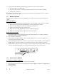
2. 5 Location of the QS3200 Switch
The QS3200 can be installed quickly and easily. However, for an installation with minimum impact on the existing
network, please read the following information carefully. Installing a QS3200 involves three steps:
1. Choosing a location
2. Supplying power
3. Connecting the switch
Consider the following criteria when selecting a location for the switch:
Avoid dusty locations
Avoid electromagnetic noisy areas, such as locations close to power transformers or radio transmitters
Avoid temperatures below 32° to 113°F (0° to 40°C)
Allow a clear view of the front panel LED indicators
Allow easy access to the front panel ports and the rear panel switches