WATERS NETWORK SYSTEMS™ INSTALLATION GUIDE AND OPERATING MANUAL ProSwitch®FlexPort- 2600M Managed Modular Copper and Fiber Switch CORPORATE HEADQUATERS MANUFACTURING/CUSTOMER SERVICE 5001 American Blvd. W., Suite 605 Bloomington, MN 55437 Phone: 800.441.5319 Phone: 952.831.5603 945 37 Avenue, NW Rochester, MN 55901 Phone: 800.328.2275 Phone: 507.285.1951 th Web site: http://www.watersnet.
TABLE OF CONTENTS 1.0 SPECIFICATIONS .....................................................................................................1 2.0 PACKAGE CONTENTS - PROSWITCH®- 2600M ...................................................3 2.1 PRODUCT DESCRIPTION .......................................................................................3 2.2 UPLINK MODULES...................................................................................................3 3.
Changing a VLAN Configuration............................................................................................13 Deleting Ports from a VLAN...................................................................................................14 Assigning PVID ......................................................................................................................14 IP Multicast Group Perspective .............................................................................................
Send File Via Kermit ..............................................................................................................29 Other Menu Functions ...........................................................................................................30 8.0 USE WEB BROWSER TO CONFIGURE 2600M ....................................................30 Logging into the 2600M .........................................................................................................
1.0 Specifications OPERATIONAL CHARACTERISTICS: MAC Address Table: Up to 2K Switching Mode: Store-and-forward Memory Buffer Size: 2 MB Filtering/Forwarding Rate Performance 10Mbps: 14,880 pps 100Mbps: 148,800 pps 1000Mbps: 1,488,000 pps MANAGEMENT OPTIONS: In-band: Web Based, SNMP, Telnet Out-band: Console SNMP Agent: MIB-II (RFC1213) Bridge MIB (RFC1493) RMON MIB (RFC1757, Group 1, 2, 3, 9) VLAN MIB (802.1Q) IEEE 802.1D VLAN: Port-based/802.
COPPER CABLE/CONNECTORS: Twisted Pair Shielded RJ45 Console Port: 4RS232 Cable/DB9 connector FIBER CABLE/CONNECTORS: Multimode FX port: 50/125um, 62.5/125mm Multimode FX port: 50/125um, 62.5/125mm Singlemode FX port: 9/125um Multimode SX/LX port: 50/125um, 62.5/125mm Singlemode SX/LX port: 9/125um, 62.
2.0 Package Contents - ProSwitch®- 2600M ProSwitch®- 2600M Two rack-mount kits and screws Console cable Installation manual 2.1 Product Description The ProSwitch®- 2600M is a high performance 10/100/1000Mbps auto-negotiation switch with SNMP/RMON web-based management capability. From a departmental backbone managing lower-level switches, hubs and workstations to high-speed switch-to-switch and switch-to-server links, the 2600M delivers outstanding performance in every environment.
1. Use the brackets and screws supplied in the rack mounting kit. 2. Use a cross-head screwdriver to attach the brackets to the side of the intelligent Switch. 3. Position the 2600M on the rack by lining up the holes in the brackets with the appropriate holes on the rack, and then use the supplied screws to mount the hub onto the standard EIA 19-inch rack. 3.
2. Remove the protective plastic covers from the fiber connectors on the module. 3. Plug the connector on the fiber cable into the fiber socket on the module. 4. Connect the other end of the fiber optic segment to an appropriate device fitted with a 100Mbps adapter. 5. Power on the switch. 6. Check the LED indicators on the front of the switch to ensure that the module is operating correctly. Removing Modules 1.
3.6 Configuration of ProSwitch®- 2600M The 2600M provides a user-friendly, menu driven console interface. Using this interface, you can perform various switch configuration and management activities, including: Configuring system and port parameters Assigning an IP address Configuring ARP Configuring DHCP relay Setting up VLAN policy Setting up packet filters Configuring STP and SNMP parameters Upgrading software 3.
Note: The 2600M does not have a default IP address. Remote management cannot be used until an IP address has been set. 4.1 Console Management Interface (CMI) You can manage the Intelligent Switch locally by connecting a VT100 terminal, or a personal computer or workstation with terminal emulation software, to the Intelligent Switch serial port. The terminal or workstation connects to the Intelligent Switch serial port using a console cable that has the appropriate connectors on each end.
Web Browser interface Telnet program This management method lets you monitor statistical counters and set switch parameters from the remote Network Management Station. Using this management method: The network must run the IP protocol. The Intelligent Switch must have an IP address Assigning an IP Address To manage the 2600M remotely through the console port or with an SNMP Management Station, you must assign an IP address to the switch.
5.1 Management Functions Basic Management Advanced Management General System Name, Software Version, Password, HTTP Enable/Disable, . . .
Configuration of LAN ports Configuration of console port Learn MAC address of switch 5.3 System Management 1. Login to the 2600M switch. 2. Select Basic Management. 3. The following menu will be displayed: 4. Select General. 5. The General Menu screen will display the current information about the 2600M switch. You can set or modify the: 6.
2. Select LAN Port. 3. Select Speed & Flow Control. 4. Select the appropriate port and make the desired changes. Use the Arrow keys and the Enter key to make your selections. 5. Press Esc to return to the Main Menu. Note: Changes are automatically saved in flash memory, so they take place immediately. So, as long as the switch is on, the settings will be saved. However, if the switch is powered down, the settings will be lost.
that is different than the network address of the switch. g. 6.0 SLIP Subnet Mask – If you are using SLIP, enter a suitable SLIP subnet mask. Advanced Management Functions VLANS 1. Login to the switch and select Advanced Management. Select L2 Switching DataBase. This menu option allows you to view and configure the switch from four perspectives: VLAN, MAC address, IP multicast group, and port.
8. The following screen is used to add switch ports to the VLAN. Press Shift and + to add a switch port number. 9. Select Tagged or Untagged. 10. Select the port number and press Enter. 11. Repeat these steps to add ports to the VLAN. 12. To remove a switch port number, highlight the port and press – (the minus key). 13. Press Esc to return to the desired menu. Deleting a VLAN 1. From the Switch Management Menu, select Advanced Management. 2. Select L2 Switching DataBase. 3.
6. Select VLAN Settings. 7. To add a port , press + (the plus key). 8. Select Tagged or Untagged. 9. Select the port number. 10. Repeat these steps to add additional ports. 11. Press Esc to return to the desired menu. Deleting Ports from a VLAN 1. From the Switch Management Menu, select Advanced Management. 2. Select L2 Switching DataBase. 3. Access the VLAN & PVID Perspective menu. 4. Select VLAN Settings. 5. Highlight an existing VLAN and press Enter. 6. Select VLAN Settings. 7.
f. Select Active. Passive mode: Passively snooping on the IGMP Query and IGMP Report. Packets are transferred between IP Multicast Routers and IP Multicast host groups to learn IP Multicast group members. Active mode: Actively sending IGMP Query messages to solicit IP Multicast group members. So, in active mode, the switch will automatically send the IGMP query messages to the network and check IGMP members. But in passive mode, the switch will not send IGMP query messages. g.
6. To view statistics for a port, highlight the desired port and press Enter. The statistics for the port you selected will be displayed. 7. Return to the Port Perspective menu. Per Port MAC Limit You can configure the MAC address learning function of each port to: Limited Learning – set a number to limit the PCs that can share this connection at the same time. Unlimited Learning – remove the PC connecting number limit. The PC connecting number on the port will become no limit.
ARP Table If you select ARP Table (Address Resolution Protocol) from the "IP Networking" screen, an ARP Table screen appears with the ARP table entries that have been already defined or learned. You can add, delete and search static entries in the ARP table. Adding Static ARP Table Entries 1. From the ARP Table screen, press Shift and press +. The Static ARP Specifications screen will be displayed. 2. Highlight the Internet Address and press Enter. The Enter Internet Address screen will be displayed. 3.
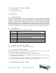
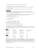
Routing Table The Routing Table allows you to view, add, delete, or search a particular routing path. The following table identifies the columns in this screen. Item Description Network The IP sub-network address to which the switch can route packets. Mask The related IP sub-network mask to which the switch can route packets. Gateway The IP address of the router at the next hop. Metric The number of hops needed between the switch and the destination network.
DHCP Gateway Setting The DHCP Gateway Settings screen provides the following information: VLAN ID - lists the IDs of the VLANs that have been defined. IP Address - displays the corresponding IP addresses of the VLANs. DHCP Relay – shows whether the DHCP relay is enabled or disabled. Max Hops - displays the maximum number of hops that a DHCP request broadcast can be relayed along the DHCP relay path from the DHCP client to the DHCP server.
configuration for the receiving IP subnet. When the DHCP server receives the DHCP request, it allocates a free IP address for the DHCP client from its scope in the DHCP client's subnet and sends a DHCP Response back to the DHCP Relay Agent. The DHCP Relay Agent then broadcasts this DHCP Response packet received from the DHCP server to the appropriate client. Pinging The following options can be set for pinging: The IP address of the host you want to ping.
The Out-Filters function will filter out packets with the source/destination addresses in the out-filters table, i.e. these packets will not be forwarded by the switch. The In-Filters function will filter in these packets with the MAC addresses in the in-filters table, i.e. these packets will always be forwarded by the switch.
Spanning Tree Path Cost This option will allow you to change the spanning tree path cost. 1. Select Spanning Tree from the Advanced Management menu. 2. Select Spanning Tree Path Costs. 3. Select the port that you want to change. 4. Enter the new path cost in the prompt screen and press Enter. 5. Press Esc to return to the desired screen. Path Cost (0 – 65535) - It is used to determine the best path between devices when there is looping.
as part of VLAN group and not VLAN grouped with the other ports. GVRP Protocol In addition to network management tools that allow network administrators to statically add and delete VLAN member ports, the 2600M supports GARP VLAN Registration Protocol (GVRP). GVRP supports the dynamic registration of VLAN port members within a switch and across multiple switches.
2. Select a trunk group and press Enter. 3. Pres Enter to select the range. 4. Use the Enter key to mark each port. 5. Press Esc to return to the menu when you are finished. Port Mirroring Port Mirroring allows you to mirror one port to another port for network traffic monitoring. 1. From the Advanced Management menu, highlight Port Mirroring and press Enter. 2. Highlight one index and press Enter. 3. Highlight Mirror To and press Enter. Select the appropriate port. 4.
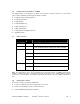
QoS Status – Use this function to enable or disable QoS. QoS is enabled by default. DiffServ Expedite Forwarding – Use this function to enable or disable DiffServ EF. This switch can map IETF DifferServ classes to its priority classes and transfer DiffServ packets with the following queue mapping: Tx Queues P3 P2 P1 P0 IETF NM+EF AF0 AF1 BE0 Note: DiffServ is the abbreviation for "Differentiated Service".
Logical Port The Logical Port function from the QoS Setup menu allows you to configure the QoS operation of different TCP/IP logical (service) ports. There are three types of logical ports can be configured: User-Defined Port - Eight user-defined TCP/IP logical ports can be set for the User-Defined Port QoS operation. Once you select a logical port and assigned a TCP/IP port number, you can configure the following: o Enable / Disable it. o Configure the drop rate to high drop rate or low drop rate.
allocation for these queues. In WFQ mode, frame latency as delay bound is not assured. Best Effort (BE) - In BE mode, a queue only receives bandwidth when none of the other classes have any traffic. It is used for non-essential traffic because there are no assurances about BE performance.
support four active profiles, so if you enable this profile, other active profiles might be disabled by the switch. Bandwidth Partition – Allows you to set the bandwidth allocation for the four transmit queues on ports for Weight Fair Queue operation. QoS with Flow Control - The flow control operation on port may conflict with the QoS operation because the flow control operation will pause the packets sent from the connected device to prevent packet loss when the port is busy.
7.0 File Transfer Use this menu to download the software running in the switch. If you select File Transfer from the Advanced Management screen, the Software Upgrade screen appears. Files can be transferred with TFTP (through network connection) or Kermit (through console connection) protocols. Highlight the method of choice and press Enter to start file transfer. Note: The software file in the switch is divided into five modules.
3. Then select Yes or No to confirm the file transfer via Kermit. 4. Start the file transfer (receive) operation in the terminal program with Kermit protocol. Other Menu Functions The remaining menu options provide the following functions: Logout – Use to logout of switch. Save Settings – All settings in the configuration process will take effect immediately. But, they will be lost once the power is turned off. To save them, use this function to save the settings to the flash chip.
Performing Basic Management Activities You can perform basic configuration/management with the Basic Setup button on the homepage. This function is very similar to the Basic Management function in the console interface. Refer to Section 5.2 for the details of basic management. Performing Advanced Management Activities You can perform advanced configuration/management with the Advanced Setup button on the homepage. This function is very similar to the Advanced Management function in the console interface.
SNMP Agent and MIB-2 (RFC1213) The SNMP Agent running on the switch manager CPU is responsible for: Retrieving MIB counters from various layers of software modules according to the SNMP GET/GET NEXT frame messages. Setting MIB variables according to the SNMP SET frame message.
This group is applicable to any type of bridge which performs destination-address filtering. 11.0 Troubleshooting All Waters’ switching products are designed to provide reliability and consistently high performance in all network environments. The installation of Waters’ ProSwitch®- 2600M switch is a straightforward procedure discussed in Section 3; the operation is also straightforward and is discussed in Section 4.
11.2 Return Material Authorization (RMA) Procedure All returns for repair must be accompanied by a Return Material Authorization (RMA) number. To obtain an RMA number, call Waters Network Systems Customer Service at 800.328.2275 during business hours from 8:00 am to 5:00 pm (CT) email carolynl@watersnet.com.
11.4 Warranty Waters Network Systems’ Warranty Statement Waters Network Systems’ products are warranted against defects in materials and workmanship. The warranty period for each product will be provided upon request at the time of purchase. Unless otherwise stated, the warranty period is for the useable life of the product.