
Specifications

Waters Network Systems User’s Manual Page 9
GSM-2108/GSM-1008SFP
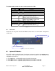
The following table provides the status and description of the LEDs:
LED Color Function
System LED
POWER Green Lit when +5V DC power is on and good
CPU LED Green Blinks when CPU is active
10/100/1000Ethernet TP Port 1 to 8 LED
LINK/ACT Green
Lit when connection with remote device is good
Blinks when any traffic is present
Off when cable connection is not good
10/100/1000Mbps
Green/
Amber
Lit green when 1000Mbps speed is active
Lit amber when 100Mbps speed is active
Off when 10Mbps speed is active
1000SX/LX Gigabit Fiber Port 7, 8 LED
SFP(LINK/ACT) Green
Lit when connection with the remote device is good
Blinks when any traffic is present
Off when module connection is not good
Table 3-1
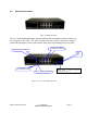
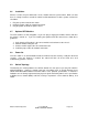
3.4 Rear Panel
Located on the rear panel is the RS-232 DB-9 interface which is used for switch management
configuration.
3.5 Optional SFP Modules
If the SFP modules are installed, ports 7 and 8 can no longer be used for 10/100/1000 copper
connection. The following lists the SFP modules that are available for the GSM2108 and
GSM1008-2SFP switches:
SFP-1000SX-LC – multimode fiber transceiver with LC connector
SFP-1000LX-LC-10 – singlemode (10km) fiber transceiver with LC connector
SFP-1000LX-LC-30 – singlemode (30km) fiber transceiver with LC connector
Figure 3.3 - Rear View of GSM-2108
RS-232 DB-9 Connector
AC Line 100-240V 50/60 Hz