Impression Series and Impression Plus Series ® ® Metered Water Softeners
TABLE OF CONTENTS Preinstallation Instructions for Dealers . . . . . . . . . . . . . . . . . . . . . . . . . . . .3 Bypass Valve . . . . . . . . . . . . . . . . . . . . . . . . . . . . . . . . . . . . . . . . . . . . . . . .3-4 Installation . . . . . . . . . . . . . . . . . . . . . . . . . . . . . . . . . . . . . . . . . . . . . . . . . .5-6 Programming Procedures . . . . . . . . . . . . . . . . . . . . . . . . . . . . . . . . . . . . . .7-8 Operating Displays and Instructions . . . . . . . . . . . . . . .
PREINSTALLATION INSTRUCTIONS FOR DEALERS: The manufacturer has preset the water treatment unit’s sequence of cycles, cycle times, salt dose, exchange capacity and salt dose refill time. The dealer should read this page and guide the installer regarding hardness, day override, and time of regeneration, before installation. For the installer, the following must be used: • Program Installer Settings: Hardness, Day Override (preset to 12 days), and Time of Regeneration (preset to 2 a.m.
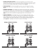
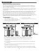
1. NORMAL OPERATION POSITION: The inlet and outlet handles point in the direction of flow indicated by the engraved arrows on the control valve. Water flows through the control valve for normal operation of a water softener. During the regeneration cycle this position provides regeneration water to the unit, while also providing untreated water to the distribution system (Fig. 1). 2. BYPASS POSITION: The inlet and outlet handles point to the center of the bypass.
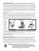
INSTALLATION: GENERAL INSTALLATION & SERVICE WARNINGS The control valve, fittings and/or bypass are designed to accommodate minor plumbing misalignments. There is a small amount of “give” to properly connect the piping, but the water softener is not designed to support the weight of the plumbing. Do not use Vaseline, oils, other hydrocarbon lubricants or spray silicone anywhere. A silicone lubricant may be used on black “O” Rings, but is not necessary.
. INLET/OUTLET PLUMBING: Be sure to install Bypass Valve onto main control valve before beginning plumbing. Make provisions to bypass outside hydrant and cold hard water lines at this time. Install an inlet shutoff valve and plumb to the unit’s bypass valve inlet located at the right rear as you face the unit. There are a variety of installation fittings available. They are listed under Installation Fitting Assemblies, page 24-25.
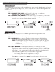
PROGRAMMING PROCEDURES: 1. Set time of day: Time of day should only need to be set after extended power outages or when daylight saving time begins or ends. If an extended power outage occurs, the time of day will flash on and off indicating that the time should be reset. STEP 1 – Press SET CLOCK. STEP 2 – CURRENT TIME (HOUR): Set the hour of the day using + or — buttons. AM/PM toggles after 12. Press NEXT to go to step 3. STEP 3 – CURRENT TIME (MINUTES): Set the minutes using + or — buttons.
2. Programming cont’d: STEP 4 – REGENERATION HOUR: The manufacturer has factory set 2:00 A.M. as the default. This is the hour of day for regeneration and can be reset by using + or — buttons. “AM/PM” toggles after 12. The default time is 2:00 a.m. (recommended for a normal household). Press NEXT to go to step 5. Press REGEN if you need to return to the previous step. STEP 5 – REGENERATION MINUTES: Set the minutes using + or — buttons. Press NEXT to exit installer programming.
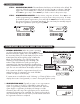
3. MANUAL REGENERATION: Sometimes there is a need to regenerate before the control valve calls for it. This may be needed if a period of heavy water use is anticipated or when the system has been operated without salt. • To initiate a manual regeneration at the next preset regeneration time, press and release REGEN. The words “REGEN TODAY” will flash on the display to indicate that the system will regenerate at the next regeneration time (set in Programming, steps 4 and 5).
5. ERROR MESSAGE: If the word “ERROR” and a number are alternately flashing on the display record the number and contact the dealer for help. This indicates that the control valve was not able to function properly. ERROR 6. BRINE TANK MAINTENANCE AND SALT: Refill the brine tank as necessary, making sure at least 1/3 of the brine tank is full at all times. Without proper salt levels, the water softener may not operate properly.
START-UP INSTRUCTIONS: • • • • After installation is complete, rotate bypass handles to bypass mode (see Fig.2 on page 4). Turn on water and check for leaks. Fully open a cold water faucet — preferably a laundry sink or bathtub without an aerator. Allow water to run until clear to rid pipes of debris which may have occurred during installation. System regeneration sequence is in the following order. (If it is desired to change this sequence, please refer to the Dealer Manual or contact the manufacturer.
TROUBLESHOOTING GUIDE: PROBLEM 1. No display on PC board 2. PC board does not display correct time of day 3. Display does not indicate that water is flowing. Refer to user instructions for how the display indicates water is flowing. 4. Control valve regenerates at wrong time of day 5. Time of day flashes on and off CAUSE CORRECTION A. No power at electric outlet A. Repair outlet or use working outlet B.
PROBLEM 7. Control valve does not regenerate automatically but does when the correct button(s) is depressed and held. For timeclock valves the buttons are ▲ & ▼. For all other valves the button is REGEN. 8. Hard or untreated water is being delivered 9. Control valve uses too much regenerant 10. Residual regenerant being delivered to service 11. Excessive water in regenerant tank CAUSE CORRECTION A. Bypass valve in bypass position A. Turn bypass handles to place bypass in service position B.
TROUBLESHOOTING GUIDE cont’d: PROBLEM 12. Control valve fails to draw in regenerant 13. Water running to drain 14. E1, Err – 1001, Err – 101 = Control unable to sense motor movement 15. E2, Err – 1002, Err – 102 = Control valve motor ran too short and was unable to find the next cycle position and stalled CAUSE CORRECTION A. Injector is plugged A. Remove injector and clean or replace B. Faulty regenerant piston B. Replace regenerant piston C. Regenerant line connection leak C.
PROBLEM CAUSE CORRECTION A. Motor failure during a regeneration 16. E3, Err – 1003, Err – 103 = Control valve B. Foreign matter built up on piston and stack motor ran too long and assemblies creating friction and drag enough was unable to find the to time out motor next cycle position C. Drive bracket not snapped in properly and out enough that reduction gears and drive gear do not interface 17. E4, Err – 1004, Err – A.
REPLACEMENT PARTS: FRONT COVER AND DRIVE ASSEMBLY Item No. 1 Part No. Description Qty.
REPLACEMENT PARTS: 1 13 14 5 4 7 9 3 8 2 10 11 PISTON ASSEMBLY Item No. Part No. Description Qty. CV3005 1" spacer stack assembly 1 CV3430 1.25" spacer stack assembly 1 2 CV3004 Drive cap assembly 1 3 CV3135 O-ring 228 1 CV3011 1" piston assembly downflow 1 1 4 1" piston assembly upflow 1 CV3407 1.
REPLACEMENT PARTS: BYPASS VALVE Item No. Part No. 1 2 3 4 5 6 7 8 9 10 CV3151 CV3150 CV3105 CV3145 CV3146 CV3147 CV3148 CV3152 CV3155 CV3156 Description Qty.
REPLACEMENT PARTS: INJECTOR ASSEMBLIES Item No. Part No.
REPLACEMENT PARTS: DRAIN LINE ASSEMBLY 3/4" Item No. Part No. 1 CH4615 2 CPKP10TS8-BULK 3 CV3192 4 CV3158-01 5 CV3163 6 7 8 CV3159-01 Description Elbow locking clip 1 Optional insert, 5/8" tube 1 Optional nut, 3/4" drain elbow 1 Drain elbow, 3/4" NPT with O-ring 1 O-ring 019 1 DLFC retainer assembly 1 CV3162-007 0.7 DLFC for 3/4" elbow CV3162-010 1.0 DLFC for 3/4" elbow CV3162-013 1.3 DLFC for 3/4" elbow CV3162-017 1.7 DLFC for 3/4" elbow CV3162-022 2.
REPLACEMENT PARTS: WATER METER & METER PLUG Item No. Part No. Description Qty. 1 CV3151 Nut, 1" QC 1 2 CV3003 Meter assembly, includes items 3 & 4 1 3 CV3118-01 Turbine assembly 1 4 CV3105 O-ring 215 1 5 CV3003-01 Meter plug assembly 1 6 CV3013 Optional mixing valve 1 SERVICE WRENCH - CV3193-02 Although no tools are necessary to assemble or disassemble the valve, the Service Wrench, (shown in various positions on the valve) is available to aid in assembly or disassembly.
REPLACEMENT PARTS: BRINE TANK ASSEMBLY Item No. Part No. CG2191- 84 CG2180 CH1072-01 2 CH1080 CG21833CB1C00 3 CG21840CB1C00 CG22441CB1C00 CH1030-27 4 CH1030-34.5 5 CH1018 6 CH4500-48 7 CH4640-32 8 CH4600-50 9 CH7016 10 CH4626 ASSEMBLIES CH4700-27WR-1 11 CH4700-34.5WR-1 1 Description Qty.
REPLACEMENT PARTS: CABINET BRINE TANK ASSEMBLY Item No. Part No. 1 CG 2197-01 2 CG2724HP-01 3 Description Qty. Salt and tank cover (must be ordered together 1 Windsor cabinet, white with black lids 1 CH1090-01 Optional salt grid for 8" diameter tank and 4" brine well 1 CH1090-02 Optional salt grid for 9" diameter tank and 4" brine well 1 CH1090-03 Optional salt grid for 10" diameter tank and 4" brine well 1 1 See opposite page for safety float system parts.
INSTALLATION FITTING ASSEMBLIES: 1" PVC MALE NPT ELBOW Item No. 1 2 3 4 Part No. Description CV3007 CV3151 CV3150 CV3105 CV3149 1" PVC male NPT elbow assembly Nut, 1" quick connect Split ring O-ring 215 Fitting 3/4" & 1" PVC SOLVENT ELBOW Item No. Qty. 2 2 2 2 2 1 2 3 4 1" BRASS SWEAT Item No. 1 2 3 4 Part No. CV3007- 02 CV3151 CV3150 CV3105 CV3188 Description 1" brass sweat assembly Nut, 1" quick connect Split ring O-ring 215 Fitting 1 2 3 4 Part No.
1-1/4" & 1-1/2" BRASS SWEAT Item No. 1 2 3 4 1-1/4" & 1-1/2" PVC SOLVENT Part No. Description Qty. CV3007- 09 CV3151 CV3150 CV3105 CV3375 1-1/4 & 1-1/2" brass sweat assembly Nut, 1" quick connect Split ring O-ring 215 Fitting 2 2 2 2 2 Item No. 1 2 3 4 3/4" BRASS SHARK BITE Item No. 1 2 3 4 Part No. CV3007-12 CV3151 CV3150 CV3105 CV3628 Description 3/4" brass Shark Bite assembly Nut, 1" quick connect Split ring O-ring 215 Fitting 1 2 3 4 Part No.
SPECIFICATIONS: CAPACITY SPECIFICATIONS IM-844 MODEL Capacity: (Grains/Lbs. NaCI) 1 Maximum Medium Minimum Amount of Media (Cu. Ft.) Maximum Water Hardness (GPG) 2 Maximum Iron (PPM) Minimum pH Required 3 Peak Flow Rate (GPM @ P-PSI) Continuous Flow Rate (GPM @ P-PSI) Water Pressure Range (PSI) Water Temp. (ºF) Electrical Requirements (volts-hertz) Pipe Size Total Dimensions: Media Tank Brine Tank Depth IM-1044 IM-1054 25,600 @ 9.0 32,000 @ 15.0 48,800 @ 21.0 21,600 @ 6.0 28,400 @ 9.0 44,400 @ 15.
Water Conditioner Limited Warranty Congratulations. You have purchased one of the finest water treatment systems available. In the unlikely event of a problem due to defects in material and workmanship, we proudly warrant our water conditioners to the original owner, when installed in accordance with Water-Right® specifications.
QUICK REFERENCE GUIDE: GENERAL OPERATION MANUAL REGENERATION When the system is operating, one of three displays will be shown: time of day, gallons of treated water available, or gallons per minute. Pressing NEXT will toggle between the three choices. NOTE: For softeners, if brine tank does not contain salt, fill with salt and wait at least two hours before regeneration.