
Troubleshooting guide


6
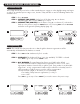
6. INLET/OUTLET PLUMBING: Be sure to install Bypass Valve onto main control valve before
beginning plumbing. Make provisions to bypass outside hydrant and cold hard water lines at this
time. Install an inlet shutoff valve and plumb to the unit’s bypass valve inlet located at the right rear
as you face the unit. There are a variety of installation fittings available. They are listed under
Installation Fitting Assemblies, page 22-23. When assembling the installation fitting package (inlet
and outlet), connect the fitting to the plumbing system first and then attach the nut, split ring and “O”
Ring. Heat from soldering or solvent cements may damage the nut, split ring or “O” Ring. Solder
joints should be cool and solvent cements should be set before installing the nut, split ring and “O”
Ring. Avoid getting solder flux, primer, and solvent cement on any part of the “O” Rings, split rings,
bypass valve or control valve. If the building’s electrical system is grounded to the plumbing, install a
copper grounding strap from the inlet to the outlet pipe. Plumbing must be done in accordance with
all applicable local codes.
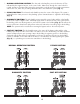
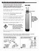
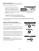
7. DRAIN LINE: First, be sure that the drain can handle the backwash rate of the system. Solder joints
near the drain must be done prior to connecting the drain line flow control fitting. Leave at least 6"
between the drain line flow control fitting and solder joints. Failure to do this could cause interior
damage to the flow control. Install a 1/2" I.D. flexible plastic tube to the Drain Line Assembly or
discard the tubing nut and use the 3/4" NPT fitting for rigid pipe (recommended). If the backwash
rate is greater than 7 gpm, use a 3/4" drain line. Where the drain line is elevated but empties into
a drain below the level of the control valve, form a 7" loop at the discharge end of the line so that
the bottom of the loop is level with the drain connection on the control valve. This will provide an
adequate anti-siphon trap. Piping the drain line overhead <10 ft is normally not a problem. Be sure
adequate pressure is available (40-60 psi is recommended). Where the drain empties into an
overhead sewer line, a sink-type trap must be used. Run drain tube to its discharge point in
accordance with plumbing codes. Pay special attention to codes for air gaps and anti-siphon devices.
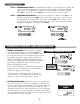
Note: The drain connection for an IMS sulfur filter or an IMB iron filter must be
secured to the floor or wall where unit discharges to drain. Because high volumes
of air and water discharge during backwash, the drain line can move violently.
Rigid pipe should be used.
CAUTION: Never insert a drain line into a drain, sewer
line, or trap. Always allow an air gap between
the drain line and the wastewater to prevent
the possibility of sewage being back-siphoned
into the filter.