Impression Series and Impression Plus Series ® ® Water Filters
TABLE OF CONTENTS Preinstallation Instructions for Dealers . . . . . . . . . . . . . . . . . . . . . . . . . . . .3 Bypass Valve . . . . . . . . . . . . . . . . . . . . . . . . . . . . . . . . . . . . . . . . . . . . . . . .3-4 Installation . . . . . . . . . . . . . . . . . . . . . . . . . . . . . . . . . . . . . . . . . . . . . . . . . .5-7 Programming Procedures . . . . . . . . . . . . . . . . . . . . . . . . . . . . . . . . . . . . . .8-9 Operating Displays and Instructions . . . . . . . . . . . . . . .
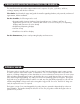
PREINSTALLATION INSTRUCTIONS FOR DEALERS: The manufacturer has preset the water treatment unit’s sequence of cycles, cycle times, salt dose, exchange capacity and salt dose refill time. The dealer should read this page and guide the installer regarding hardness, day override, and time of regeneration, before installation. For the installer, the following must be used: • Program Installer Settings: Hardness, Day Override (preset to 12 days), and Time of Regeneration (preset to 2 a.m.
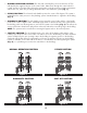
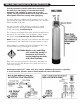
1. NORMAL OPERATION POSITION: The inlet and outlet handles point in the direction of flow indicated by the engraved arrows on the control valve. Water flows through the control valve for normal operation of a water filter. During the regeneration cycle this position provides regeneration water to the unit, while also providing untreated water to the distribution system (Fig. 1). 2. BYPASS POSITION: The inlet and outlet handles point to the center of the bypass.
INSTALLATION: GENERAL INSTALLATION & SERVICE WARNINGS The control valve, fittings and/or bypass are designed to accommodate minor plumbing misalignments. There is a small amount of “give” to properly connect the piping, but the water filter is not designed to support the weight of the plumbing. Do not use Vaseline, oils, other hydrocarbon lubricants or spray silicone anywhere. A silicone lubricant may be used on black “O” Rings, but is not necessary.
. INLET/OUTLET PLUMBING: Be sure to install Bypass Valve onto main control valve before beginning plumbing. Make provisions to bypass outside hydrant and cold hard water lines at this time. Install an inlet shutoff valve and plumb to the unit’s bypass valve inlet located at the right rear as you face the unit. There are a variety of installation fittings available. They are listed under Installation Fitting Assemblies, page 22-23.
IMS/IMB INSTALLATION INSTRUCTIONS: Special precautions must be made when connecting the drain line. Hard piping is recommended. During backwash, high volumes of water and air escape rapidly, causing a flexible drain line to whip and thrash. Please attach drain line securely with rigid piping. Two check valves are supplied with this shipment. One is a 3/8" John Guest push-in type with screen and the other is a 1" stainless female threaded check valve.
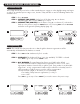
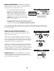
PROGRAMMING PROCEDURES: 1. Set time of day: Time of day should only need to be set after extended power outages or when daylight saving time begins or ends. If an extended power outage occurs, the time of day will flash on and off indicating that the time should be reset. STEP 1 – Press SET CLOCK. STEP 2 – CURRENT TIME (HOUR): Set the hour of the day using + or — buttons. AM/PM toggles after 12. Press NEXT to go to step 3. STEP 3 – CURRENT TIME (MINUTES): Set the minutes using + or — buttons.
2. Programming cont’d: STEP 4 – REGENERATION HOUR: The manufacturer has factory set 12:00 A.M. as the default. This is the hour of day for regeneration and can be reset by using + or — buttons. “AM/PM” toggles after 12. The default time is 12:00 a.m. (recommended for a normal household). Press NEXT to go to step 5. Press REGEN if you need to return to the previous step. STEP 5 – REGENERATION MINUTES: Set the minutes using + or — buttons. Press NEXT to exit installer programming.
3. MANUAL REGENERATION: Sometimes there is a need to regenerate before the control valve calls for it. This may be needed if a period of heavy water use is anticipated or when the system has been operated without salt. • To initiate a manual regeneration at the next preset regeneration time, press and release REGEN. The words “REGEN TODAY” will flash on the display to indicate that the system will regenerate at the next regeneration time (set in Programming, steps 4 and 5).
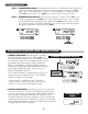
START-UP INSTRUCTIONS: • • • • After installation is complete, rotate bypass handles to bypass mode (see Fig.2 on page 4). Turn on water and check for leaks. Fully open a cold water faucet — preferably a laundry sink or bathtub without an aerator. Allow water to run until clear to rid pipes of debris which may have occurred during installation. System regeneration sequence is in the following order. Some sequence differences may be noticed depending upon local conditions.
REPLACEMENT MINERAL INSTRUCTIONS FOR IMBF-ACID NEUTRALIZER: The IMBF-Acid Neutralizer utilizes a sacrificing mineral that will need replacement every 6 to 12 months. • Check mineral for proper height every 6 months. • If below half-full, add mineral to the two-thirds full level. (NEVER OVERFILL PAST TWO-THIRDS FULL.) • Always turn water supply off and relieve water pressure before opening unit. (See instructions stated below.) 1.
TROUBLESHOOTING GUIDE: PROBLEM Timer does not display time of day Timer does not display correct time of day or time of day flashes No softening/ filtering display when water is flowing CAUSE CORRECTION A. transformer unplugged A. reconnect transformer B. no power at outlet B. repair or use working outlet C. defective transformer C. replace transformer D. defective PC board D. replace PC board A. outlet is on a switch A. use unswitched outlet B. power outage B.
PROBLEM Valve does not regenerate automatically when REGEN button is pressed Valve does not regenerate automatically but does when REGEN button is pressed CAUSE CORRECTION A. transformer unplugged A. connect transformer and PC board power B. no power at outlet B. restore power C. broken drive gear or drive cap assembly C. replace gear or drive cap assembly D. defective PC board D. replace board A. bypass valve not in normal operating mode A. see bypass diagrams on page 4 B.
REPLACEMENT PARTS: FRONT COVER AND DRIVE ASSEMBLY Item No. 1 Part No. Description Qty.
REPLACEMENT PARTS: 1 13 14 5 4 7 9 3 8 2 10 11 12 PISTON ASSEMBLY Item No. Part No. Description Qty. CV3005 1" spacer stack assembly 1 CV3430 1.25" spacer stack assembly 1 2 CV3004 Drive cap assembly 1 3 CV3135 O-ring 228 1 CV3011 1" piston assembly downflow 1 1 4 1" piston assembly upflow 1 CV3407 1.
REPLACEMENT PARTS: BYPASS VALVE Item No. Part No. 1 2 3 4 5 6 7 8 9 10 CV3151 CV3150 CV3105 CV3145 CV3146 CV3147 CV3148 CV3152 CV3155 CV3156 Description Qty.
REPLACEMENT PARTS: INJECTOR ASSEMBLIES Item No. Part No.
REPLACEMENT PARTS: DRAIN LINE ASSEMBLY 3/4" Item No. Part No. 1 CH4615 2 CPKP10TS8-BULK 3 CV3192 4 CV3158-01 5 CV3163 6 7 8 CV3159-01 Description Elbow locking clip 1 Optional insert, 5/8" tube 1 Optional nut, 3/4" drain elbow 1 Drain elbow, 3/4" NPT with O-ring 1 O-ring 019 1 DLFC retainer assembly 1 CV3162-007 0.7 DLFC for 3/4" elbow CV3162-010 1.0 DLFC for 3/4" elbow CV3162-013 1.3 DLFC for 3/4" elbow CV3162-017 1.7 DLFC for 3/4" elbow CV3162-022 2.
REPLACEMENT PARTS: WATER METER & METER PLUG Item No. Part No. Description Qty. 1 CV3151 Nut, 1" QC 1 2 CV3003 Meter assembly, includes items 3 & 4 1 3 CV3118-01 Turbine assembly 1 4 CV3105 O-ring 215 1 5 CV3003-01 Meter plug assembly 1 6 CV3013 Optional mixing valve 1 SERVICE WRENCH - CV3193-01 Although no tools are necessary to assemble or disassemble the valve, the Service Wrench, (shown in various positions on the valve) is available to aid in assembly or disassembly.
INSTALLATION FITTING ASSEMBLIES: 1" PVC MALE NPT ELBOW Item No. 1 2 3 4 Part No. Description CV3007 CV3151 CV3150 CV3105 CV3149 1" PVC male NPT elbow assembly Nut, 1" quick connect Split ring O-ring 215 Fitting 3/4" & 1" PVC SOLVENT ELBOW Qty. 2 2 2 2 2 Item No. 1 2 3 4 1" BRASS SWEAT Item No. 1 2 3 4 Part No. CV3007- 02 CV3151 CV3150 CV3105 CV3188 Description 1" brass sweat assembly Nut, 1" quick connect Split ring O-ring 215 Fitting Part No. Description Qty.
1" PLASTIC MALE NPT Item No. 1 2 3 4 Part No. CV3007- 04 CV3151 CV3150 CV3105 CV3164 Description 1" plastic male NPT assembly Nut, 1" quick connect Split ring O-ring 215 Fitting 1-1/4" PLASTIC MALE Qty. 2 2 2 2 2 Item No. 1 2 3 4 1-1/4" & 1-1/2" BRASS SWEAT Item No. 1 2 3 4 Part No. CV3007- 05 CV3151 CV3150 CV3105 CV3317 Description 1-1/4" plastic male assembly Nut, 1" quick connect Split ring O-ring 215 Fitting Qty. 2 2 2 2 2 1-1/4" & 1-1/2" PVC SOLVENT Part No. Description Qty.
SPECIFICATIONS: NEUTRALIZER SPECIFICATIONS MODEL NUMBER IMBF1044MAN IMBF1054MAN IMBF1354MAN IMAN-1044 IMAN-1054 IMAN-1354 CALCITE or MIX 1.0 CALCITE or MIX 1.5 CALCITE or MIX 2.5 CALCITE or MIX 1.0 CALCITE or MIX 1.5 CALCITE or MIX 2.5 14 lb 1/4 x 1/8 7 lb. #20 14 lb 1/4 x 1/8 7 lb. #20 21 lb1/4 x 1/8 7 lb. #20 14 lb 1/4 x 1/8 7 lb. #20 14 lb 1/4 x 1/8 7 lb. #20 21 lb 1/4 x 1/8 7 lb. #20 Cont. Flow Peak Flow 5.0 8.0 5.0 9.0 6.0 12.0 5.0 8.0 5.0 9.0 6.0 12.0 Backwash Flow GPM 5.
QUICK REFERENCE GUIDE: GENERAL OPERATION MANUAL REGENERATION When the system is operating, one of three displays will be shown: time of day, gallons of treated water available, or gallons per minute. Pressing NEXT will toggle between the three choices. NOTE: If you need to initiate a manual regeneration, either immediately, or the same night at the preprogrammed time for regeneration (typically 12:00 AM), complete the following steps.