
Operating instructions


26
45
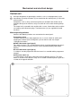
Mechanical and electrical design
0420
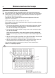
Fig.
45
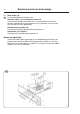
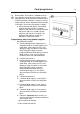
Replacement and adjustment of micro switches
After removing the two wire connection sockets at the top of the programmer,
remove the two screws holding back the black cover plate over the microswitches
and the plate (A). Turn the knob. Lift up the defective microswitch and replace it
by a new one. Mount the cover plate.
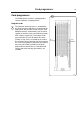
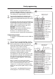
A special test card is used to check and correct the adjustment of the card
programmer microswitches.
Coloured dots indicate various positions on the card.
Please follow the instructions shown below when using this testcard to adjust the
programmer microswitches:
1. Turn the knob fully clockwise and insert the card into the programmer with the
track side up and the unnumbered side first, until the green dot one card is
even with the front edge of the programmer.
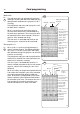
2. Turn the knob fully counter-clockwise and push the card in until the blue dot is
even with the front edge.
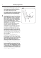
Check that all microswitches make contact between the blue and white dot.
Readjust if necessary by using a thin screwdriver on the individual adjustment
screws.
3. Slide the card out until the green dot is even with the front edge. Check that no
switches have switched contact to this pint. Adjust if necessary.
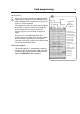
4. Slide the card further out until the blue dot is even with front edge. Check that
all microswitches have now switched over. Readjust if necessary.
This procedure should be repeated at least twice to make certain that the
switches are all properly adjusted.