
Operating instructions


7
Installation
0277
Electrical installation
Although the machines are fitted with thermal
overloads in the motor windings and separate
fuses for the control circuit, a separate three-
phase common-trip circuit breaker must be
installed for all three-phase machines.
For proper overcurrent protection, check the data
plate at the rear of the machine. Also consult local
electrical code for special requirements.
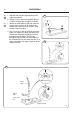
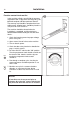
Connect L1, L2, L3 and ground wires according to
the markings of the terminal block. The cable is to
hang in a large loose loop, supported by the clip of
the terminal block. After installation, do the
following:
Check the incoming power for a high voltage leg. If
present, connect that line to L2 on the terminal
block.
Start the machine and check that the drum rotates
in the proper direction during extraction, i.e.
counter-clockwise when seen from the front. If the
drum rotates in the wrong direction interchange
line L1 and L3 at the power connection terminal.
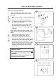
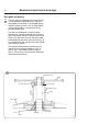
Connection for signals to external liquid supply
injector
On the right side of the terminal connection is the
connection for signals. Depending on the number
of pumps to be connected, they shall be
connected from 1–5 and C (Common) on resp.
connection. The signal wires can take max. 0,5 A
total output load.
The pumps obtain 220V signals from the program
card via the connections.
Rib A controls connection 1
Rib C controls connection 2
Rib E controls connection 3
Rib G controls connection 4
Rib I controls connection 5
NOTE
Remember that it is only a signal which is
obtained from the machine to the pumps and
not time controlling.
From the smaller connection block a power feed of
max 6A output load can be obtained.
Fig.
10
Fig.
11
Fig.
12
11
10
Fig.
13
2642a
13
2642b
12
1760