OPERATING & MAINTENANCE MANUAL FLEX-O-MATIC EXSM 350 471 1562-95/03 97.44 WARNING: ALL OPERATING AND MAINTENANCE PROCEDURES SHOWN ON THE NEXT PAGE OF THIS MANUAL MUST BE FOLLOWED DAILY FOR PROPER OPERATION OF YOUR WASCOMAT MACHINE. PLEASE ENTER THE FOLLOWING INFORMATION AS IT APPEARS ON THE MACHINE(S) DATA PLATE(S). MACHINE TYPE OR MODEL MACHINE SERIAL NUMBER(S) ELECTRICAL CHARACTERISTICS: ________ VOLTS, _______ PHASE, _______ HZ.
II NOTICE TO: OWNERS, OPERATORS AND DEALERS OF WASCOMAT MACHINES IMPROPER INSTALLATION AND INADEQUATE MAINTENANCE, POOR HOUSEKEEPING AND WILLFUL NEGLECT OR BYPASSING OF SAFETY DEVICES MAY RESULT IN SERIOUS ACCIDENTS OR INJURY. TO ASSURE THE SAFETY OF CUSTOMERS AND/OR OPERATORS OF YOUR MACHINE, THE FOLLOWING MAINTENANCE CHECKS MUST BE PERFORMED ON A DAILY BASIS. 1.
SAFETY AND WARNINGS SIGNS Replace If Missing Or Illegible One or more of these signs must be affixed on each machine as indicated, when not included as part of the front instruction panel. LOCATED ON THE OPERATING INSTRUCTION SIGN OF THE MACHINE: CAUTION PRECAUCION 1. Do not open washer door until cycle is completed, operating light is off, and wash cylinder has stopped rotating. 1.
FLEX-O-MATIC EXSM 350 Contents Introduction ...................................................................... 1 Technical data .................................................................. 2 Installation ........................................................................ 4 Safety rules .................................................................... 13 Mechanical and electrical design ................................... 14 Washing instructions ............................................
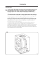
Introduction 1 Introduction The Flex-O-Matic solid mounted washer/extractor has been developed to cover the heavy duty requirements of hotels, motels, nursing homes, hospitals, professional laundries, restaurants, airlines, ships, schools, colleges and all on-premises laundries where flexibility and quick formula variation, coupled with high quality automatic washing, are required. Fig.
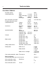
Technical data 2 Flex-O-Matic EXSM 350 Dry load capacity up to Overall dimensions Width Depth (at the top) Height Net weight Max. floor load at extraction Frequency (dynamic force) 80 lbs 1114 mm 1121 mm 1520 mm 645 kg 43 7/8'' 44 1/8'' 59 7/8'' 1422 lbs ±14 kN 10,8 Hz ±3147 lbs.force Crated Dimensions Volume Weight 2.4 m3 662 kgs 85 cu.ft 1460 lbs Inner drum Diameter Depth Volume 920 mm 520 mm 350 litre 36 1/4'' 20 1/2'' 12.6 cu.ft.
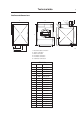
Technical data 3 Outline and dimensions C A U 4 5 6 S R P 1 T 2 B D O L M F G E 3 N 2479 H I K 1 2 3 4 5 6 Electrical cable connection Steam connection Drain connection Hot water connection Hot water connection Cold water connection EXSM 350 A B C D E F G H I K L M N O P R S T U mm inches 1114 1520 1206 597 935 66 100 490 590 930 527 120 206 1380 89 184 354 1270 125 43 7/8'' 59 7/8 47 15/32'' 23 1/2'' 36 13/16'' 2 5/8'' 3 15/16'' 19 19/64'' 23 1/4'' 36 5/8'' 20 3/4'' 4 3/4'' 8 1/
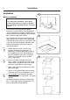
Installation 4 Installation 2 Machine foundation For making the foundation, check with a professional engineer in order to calculate the foundation regarding dynamic and static forces. The machines are designed to be bolted in position to a concrete floor or specially prepared concrete foundation. A template showing the size of the foundation and positioning of the foundation bolts is delivered with each machine.
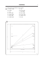
Installation 5 Measurements for foundation in inches and (mm). Fig.
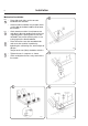
Installation 6 Mechanical installation Fig. 6 6 • Place wide steel shims on the concrete foundation over the bolts. • Lift the machine and lower it in position. Never use the door or the door handle to lift or lower the machine. Fig. 7 Fig. 8 • Check that the machine is level front-to-rear and side-to-side and standing firmly on the ten supporting points. Spacing washers must be mounted if one or more of these points is not resting against the floor/foundation.
Installation Electrical installation Fig. 10 7 10 Although the machines are fitted with thermal overloads in the motor windings and separate fuses for the control circuit, a separate threephase common-trip circuit breaker must be installed for all three-phase machines. For proper overcurrent protection, check the data plate at the rear of the machine. Also consult local electrical code for special requirements. Fig. 11 Connect L1, L2, L3 and ground wires according to the markings of the terminal block.
Installation 8 Water connection 14 NOTE All plumbing must conform to national and local plumbing codes. Fig. 14 Fig. 15 Incoming water lines do not require non-return or back-suction valves, as the machine is already fitted with a siphon breaker. However, all incoming lines must be fitted with shut-off valves. • Water inlets are labelled for connection of hot and cold water hoses. 2367 15 • Flush the water system thoroughly and check that the filter at the machine inlet is fitted correctly. Fig.
Installation Steam connection Fig. 18 9 18 The steam inlet pipe must be fitted with a manual cut-off valve in order to facilitate installation and service operations. Attach the filter supplied with the machine to the manual cut-off valve. Conncection hoses should be of the quality required according to regulations in the country of use. Connections size at filter: DN 15 (1/2''). 2369 Steam pressure required: • minimum: 50 kPa (0.
Installation 10 Fig. 22 1. Drop the knob into the larger opening in the supply manifold lid. 22 2. Tighten securely. Do not overtighten! Do not use pliers or other tools to tighten the knobs! Fig. 23 1. Stretch the multi-rubber ring B and select the correct size ring which will fit snugly on the chemical tube you are using. Ring A is used for tubes with 5/16'' diam. 2. Use scissors or a razor to carefully cut out the proper size rubber ring.
Start -up and safety checklist Start-up and safety checklist 11 24 Before initial start-up of a Wascomat washerextractor, the following safety checks must be performed: Fig. 24 Fig. 25 • Make sure the machine is properly bolted to the floor. • Make sure that all electrical and plumbing connections have been made in accordance with applicable local codes. • Use only flexible water fill and drain hoses of the proper length to avoid sags and kinks. • Make sure the machine is properly grounded electrically.
Installation 12 Function control check-out list 28 In the machine cylinder, you will find the warranty registration card, a copy of the warranty policy, the bolt hole template and other pertinent material. The warranty card should be completed and sent to Wascomat. All other items should be placed in a safe place for future reference. The machine should be cleaned when the installation is completed, and checked out as detailed below without loading the machine with fabrics: 1.
Safety rules Safety rules • The machine is designed for water washing only. • Machines must not be used by children. • All installation operations are to be carried out by qualified personnel. Licensed personnel are necessary for all electric power wiring. • The interlock of the door must be checked daily for proper operation and must not be bypassed. • All seepage in the system, due to faulty gaskets etc., must be repaired immediately.
Mechanical and electrical design 14 General The door, card programmer, thermometer, thermostat (if heated), control lights and manual switches are fitted at the front of the machine. All control and indicating components, i.e. relays, level control, etc are assembled under the top cover, easily accessible from the top of the machine for ease of servicing. Main units Fig. 30 1 ON-OFF and manual operating buttons - to start the machine and operate it manually.
Mechanical and electrical design 15 Machine construction Panels The machines are equipped with a top panel and front panel made of stainless steel. For servicing purposes, the panels can easily be removed. Outer shell Fig. 31 The outer shell is made of heavy gauge surgical steel and is attached to a heavy duty, rigid head casting (back gable). The whole assembly is mounted on a heavy gauge fabricated steel base, hot-dip galvanized for long life and corrosion resistance.
Mechanical and electrical design 16 Back gable and bearing Fig. 32 The back gable and the bearing trunnion housing are constructed of a webbed heavy casting for extra rigidity. The bearings are protected against filtration of water by three seals. An intermediate safety outlet provides an escapement for any possible condensation. The seals are mounted on a chrome-plated, noncorrosive, specially hardened sleeve bushing that is mounted on the drive shaft to prevent wear of the seals and shaft.
Mechanical and electrical design 17 Control unit Fig. 33 All major components for operating the machine, such as card programmer (3) the thermometer (4) and push-buttons (5) are mounted on the control panel (1) at the front of the machine. Components such as relays and reversing timer are mounted in the control unit (2) located at the top of the machine, easily accessible for service after removing the top panel. The control unit is mounted in the machine with 4 screws.
Mechanical and electrical design 18 Fig. 34 Drain switch (10) For manual operation of the drain valve. Hot water switch (11) and cold water switch (12) are for manual operation of the inlet valves as marked. When the machine operates automatically via the programmer, the push-buttons may be used to raise the water level, by adding water. Detergent flushing switch (13) is for manual flushing of detergent from Compartment 1. Thermostats (14), if heated Two thermostats controlling two temperatures.
Card programmer Card programmer 19 35 The EXSM 350 FL-machine is equipped with a 16 track automatic card programmer. Program cards Fig. 35 The automatic washing process is controlled by the plastic program card which is inserted into the programmer. Any number of cards may be cut to follow the formulas established by your chemical supplier for washing, rinsing and extracting needs. Each card has sixteen ribs, consisting of small pegs marked A-Q. Each rib controls one wash function.
20 Card programmer As the card proceeds through the cycle a missing peg in one of the ribs closes the circuit of the corresponding micro-switch in the programmer and activates that particular function. 36 Never cut the formula without first laying it out on the card. Mark the pegs to be eliminated and then carefully re-check it against your formula plan. Fig. 36 Cutting the pegs from the card is accomplished with a special pair of cutters, delivered with the machine, or by using a 1/4 inch chisel.
Card programmer Fig. 37 Gentle action. This feature is standard on all FL’s. You select this feature by pressing the manually operated switch on the front of the control panel. It is ideal for blankets, draperies, slipcovers, and all fragile materials where reduced mechanical action is desirable. The washer will function as follows: A During washing and rinsing, the tumbling action of the basket will be 3 seconds clockwise and stop for 12 seconds.
22 Card programming I- Flushing softener from compartment 3. Programmed for 30 seconds together with water filling. If the water pressure is low, detergent supply should occur after water filling. Detergent supply can not be programmed before water filling. If external liquid supply is used, signal is given to terminal 5 at the rear connection block. 38 K- Drain. Cut for 60 second duration. L- High speed extraction. Cut together with H if high speeed is desired. Uncut for low speed extraction.
Card programming When Cool down is programmed (rib P) the machine is filled with cold water. Th amount of time chosen depends on the temperature desired. The cooling rate is approximately 3-4°C/min. Fig. 40 Programming Extraction (rib marked H) shall always be preceded by Drain (rib marked K). This shall also be programmed during the entire extract cycle. 23 40 Extraction Drain before and during extraction A. Detergent, (1) B. Not used (heating) C. Detergent, (2) D. Not used (heating) E.
Card programming 24 Main wash Fig. 42 The main wash lasts for approximately 8 minutes and begins by filling with hot water and dispensing detergent from compartment 2 (peg no. 8 in rib C cut away). 42 Draining Washing Filling with water and detergent The programmer stops the card at peg no. 8 until the water level is reached. A. Detergent, (1) B. Not used (heating) C. Detergent, (2) D. Not used (heating) E. Extern supply F. Extern supply G. Extern supply H. Extraction I. Fabric softener, (3) K.
Card programming Rinse cycle 4 Fig. 44 Rinse cycle 4 lasts for 8 minutes and begins with Filling water to high water level and dispensing of fabric conditioner from compartment 3 (peg no. 33 in ribs N, I and O removed). The programmer stops the card at peg 33 until the water level has been reached. The running time once the water level has been reached is 2 minutes (peg nos. 33 to 36 in tibs N and O cut away). Rinse cycle 4 is concluded with Drain for 6 minutes (peg nos. 37-50 in rib K cut away).
Mechanical and electrical design 26 Replacement and adjustment of micro switches Fig. 45 After removing the two wire connection sockets at the top of the programmer, remove the two screws holding back the black cover plate over the microswitches and the plate (A). Turn the knob. Lift up the defective microswitch and replace it by a new one. Mount the cover plate. A special test card is used to check and correct the adjustment of the card programmer microswitches.
Mechanical and electrical design Reverser 27 46 Construction of reverser Fig. 46 The reversing switch unit consists of a camshaft (6) and a contact bank (5) with two alternating sets of contacts and three sets of opening contact all made of silver. The cam shaft is driven by a synchronous motor (2) via an escapement (1). The gears are made of durable plastic to ensure a long life. The contact bank is made of plastic (Melamin) resitant to current.
Mechanical and electrical design 28 Relays 48 The FL model employs seven relays. The relays control: • the wash windings of the wash motor • the distribution windings of the wash motor • the extraction motor • the drain cycle • the restart after a programmed stop • the switching back to low speed extraction if too high unbalance is indicated. Construction Fig. 48 The body of the relay holding the stationary contacts is made of current-resistant plastic.
Mechanical and electrical design Drive motors 29 49 Drive motor description Fig. 49 The four-speed operation of the wash cylinder is achieved by two motors. One 2-speed motor for wash speed (12-pole drive) and distribution speed (8-pole drive) and one 2-speed motor for extraction speeds (4-pole drive, low speed and 2-pole, high speed).
30 Mechanical and electrical design Drive motor function 50 When the stator winding is charged, a magnetic field will occur, which in turn will rotate the motor at a fixed RPM depending upon the number of poles in the winding. The 12-pole winding gives the wash speed and the 8-pole winding in the same motor gives the distribution speed. The separate 4/2-pole motor gives the extraction speeds. When operating with load, the speed deviates slightly from the synchronous (no-load) speed.
Mechanical and electrical design Motor connections Fig. 31 51 Wash/distribution motor 51 Fig. Extract motor Thermal Overload protector 52 Motor overload protector Each motor is equipped with self-resetting, thermal overload protectors, situated one in each winding of the stator. The protectors are connected in series and will trip at a temperature of 120°C (248°F).
Mechanical and electrical design 32 Repair instructions 53 Motor not running due to overheating • Wait till motor has cooled down. Motor thermal protectors are automatically reset after appr. 30 minutes. Restart. • Possible cause of motor protector releasing repeatedly could be oversensitivity of thermal protector. 111 lbt 25 N Very noisy motor 14 mm 9/16'' • Breakdown of bearings – replace bearings or motor.
Mechanical and electrical design Water level controls Fig. 54 33 54 One double-level pressure switch is used to control the correct water levels during various cycles of the washing program. A second level control is installed on the machines to prevent the machine from going into extraction until a sufficient amount of water has been drained. A third level control is instaled to prevent flushing down the soap supply box before a low level is reached.
Mechanical and electrical design 34 Supply injection valve 55 Construction Fig. 55 The valve has a single-inlet with either one, two or three outlets, each with its own solenoid coil. The body is made of heat-resistant polyamid plastic and the solenoids encased in water-tight plastic. The electrical connector terminals are spade lugs. A filter screen on the inlet side prevents dirt from entering the valve. Flow restrictors can be placed at either the inlet or any of the outlets. Operation Fig.
Mechanical and electrical design Repair instructions 35 57 Limescale can block the hole in the valve diaphragm and interfere with the function of the valve. Fig. 57 It is therefore advisable to dismantle and clean the valve at certain regular intervals. The frequency depends on operating conditions and the level of contamination in the water. If the valve does not open • Check that power is supplied to the coil.
Mechanical and electrical design 36 Inlet valve for FLEX-O-MATIC EXSM 350 Fig. 60 60 The water inlets have brass bodies with larger cross section of the outlet in order to achieve a shorter filling time for the machine. Construction Fig. 61 The valve housing is made of pressed brass. The spring-loaded plunger is made of stainless steel and located at its lower end.
Mechanical and electrical design Drain valve 37 62 Description Fig. 62 The drain valve is operated by using the pressure in the cold water intake. A tube (1) is connected between the cold water intake and a solenoid valve (2). When the solenoid valve is activated, it opens and allows water to flow into the feeder tube (3). The water presses up a piston (4), which uses the pressure lid (5) to close the drain valve rubber membrane.
Mechanical and electrical design 38 Soap supply box Fig. 63 The three-compartment soap supply box is located at the top of the machine. Viewed from the front, the compartments marked with figures 1, 2 and 3 are used as follows: For powder supplies: Compartment 1 This compartment is used for adding detergent directly to the wash at the beginning of a cycle or at any time during the cycle when extra supplies are required, controlled by rib A on the formula card.
Mechanical and electrical design 39 Door and safety locking system The door safety locking device consists of the following main parts: Fig. 64 • Locking unit. The door locking unit is placed behind the front plate and under the detergent box. The unit consist of a coil, which blocks the door, and two micro switches. Switch S3 indicates that the door is locked and switch S4 that the coil is activated. • Delay unit. The delay unit is mounted in the control unit.
Mechanical and electrical design 40 Function Fig. 65 When the door has been locked by the door handle, the locking arm is turned and activating the microswitch S3 in the locking unit. When the programmer knob is turned to position I, switch S30 is closed, the delay unit receives voltage and the coil is locking the door. And then switch S4 is closed and the program can start.
Mechanical and electrical design Fault finding The coil does not lock the door when programmer knob is turned to I. • Check that lamp in the red push button is lightning. If not, check that the emergency opening is not activated. • Check that the coil is receiving voltage and that the plunger can move freely. Check with a ohm-meter for interruption in the coil. • Check that the delay unit receives voltage.
Mechanical and electrical design 42 Rotation guard Fig. 66 The rotation guard checks that the drum is completely at a standstill before the door can be opened. When the drum has been still for approx. 2 seconds the coil in the door lock is activated and the lock can be opened (providing the water has emptied and the programmer has reset). This guard also checks that the drum is actually rotating when the wash or extraction relays are operating.
Mechanical and electrical design Fig. 43 When the machine has halted, the rotation guard relay K1 is closes which means that the door lock coil Y4 will be energised and the door can be opened. Since the wash and extraction relays are not closed, relay K3 is not energised. 67 When the machine starts and pulses are received from the pulse generator relay K1 will switch immediately and it will not be possible to open the door.
Washing instructions 44 Manual operation Fig. 68 Fig. 69 Fig. 70 68 1. When the machine is manually operated, the push button switches control the hot and cold water inlets, the gentle action cycle and the drain valve. A blank formula card must be inserted for the machine to operate. Since there is no manual switch for extraction, the formula card must be programmed for this as well as for draining prior to and during extraction. The buzzer signal at the end of the cycle must also be programmed. 2.
Washing instructions Start the wash 45 71 • Open shut-off valves for hot and cold water. Fig. 71 Fig. 72 Fig. 73 Fig. 74 • Turn on electric power and push the ’’On-Off’’ switch on the machine to ’’On’’. • Turn the black knob clockwise until white dot on knob points to small circle with black dot above. • Insert a pre-cut formula card in the programmer -the ribs facing upwards - and push the card all the way into the programmer.
Maintenance 46 Maintenance 75 Preventive maintenance has been reduced to a minimum by the careful design of reliable components and material. However, the following measures should be taken at regular intervals and in proportion to the hours of service. IMPORTANT! Make certain that all electrical power to the machine is shut off before removing top or rear panels. Daily • Check the door lock and interlock before starting operations.
Trouble-shooting The purpose of the trouble-shooting guide is to facilitate the location and correction of the most common machine problems. 47 77 Before the top panel is removed, power to the machine is to be switched off at the main source or at the separate circuit breaker. At each trouble-shooting attempt, the plug in connectors on the control panel should be moved in and out in order to eliminate improper contact due to faulty connection.
Trouble-shooting 48 If machine does not extract: Fig. 79 79 A Check extract relays and relay coil for proper operation. B Check programmer switch H. C Check the extract safety level control. D Check the reversing switch. E Check the door lock. F Check all the drain items of Section ’’If water does not drain’’ above. If motor does not operate at wash speed: Fig. 80 A Check wash relay. B Check motor and V-belt. C Check reversing mechanism.
Trouble-shooting If machine runs slowly on wash speed or there is a slapping or thumping noise: Fig. 81 49 81 Replace V-belts. If a metallic noise can be heard at rear of machine: Fig. Tighten pulley on motor shaft. 82 If the door is leaking: Fig. 83 Check door gasket. If gasket is in good condition check the tension, between door gasket and door frame and adjust.
50 Trouble-shooting If there is leaking around glass: Fig. 84 84 A Re-cement glass in door gasket, if worn. B Replace door gasket if worn. If water does not enter machine: Fig. 85 A Check the coils on inlet valves. B Check wires leading to coils. C Be sure manual shut-off valves are in open position. D Check contacts on programmer. E Check water level switch and plastic tubing. 1778 85 F Check programmer switches K, N, O and Q.
Trouble shooting If water continues to flow without stopping and programmer DOES advance: Fig. 87 51 87 A Check inlet valves for dirt underneath the valve diaphragm. To localize, shut off power. If water continues to flow, inlet valves have foreign material in them and should be thoroughly cleaned. B Check level controls. If water continues to flow without filling machine: Fig. A Check seating of drain valve. 88 Programmer does not advance: Fig. 89 A Check synchronous motor on programmer.
Trouble-shooting 52 If machine does not reverse: Fig. 90 A Check reversing mechanism. 90 If machine vibrates excessively: Fig. 91 A Tighten mounting bolts. If either safety fuse blows at the beginning of the cycle: Fig. 92 A Replace fuse. B Disconnect wires leading to the delay circuit of the door lock. Replace fuse and start. If the machine now works, replace delay circuit.
Trouble-shooting If machine vibrates excessively. Fig. 53 93 A Check the out-of-balance detector switch.