OPERATING & MAINTENANCE MANUAL EX-12 EX-22 From machine No. 91/6411- EX 12, 91/5875- EX 22 471 1562-60/01 95.38 WARNING: ALL OPERATING AND MAINTENANCE PROCEDURES SHOWN ON THE NEXT PAGE OF THIS MANUAL MUST BE FOLLOWED DAILY FOR PROPER OPERATION OF YOUR WASCOMAT MACHINE. PLEASE ENTER THE FOLLOWING INFORMATION AS IT APPEARS ON THE MACHINE(S) DATA PLATE(S). MACHINE TYPE OR MODEL MACHINE SERIAL NUMBER(S) ELECTRICAL CHARACTERISTICS: ________ VOLTS, _______ PHASE, ______ HZ.
II NOTICE TO: OWNERS, OPERATORS AND DEALERS OF WASCOMAT MACHINES IMPROPER INSTALLATION AND INADEQUATE MAINTENANCE, POOR HOUSEKEEPING AND WILLFUL NEGLECT OR BYPASSING OF SAFETY DEVICES MAY RESULT IN SERIOUS ACCIDENTS OR INJURY. TO ASSURE THE SAFETY OF CUSTOMERS AND/OR OPERATORS OF YOUR MACHINE, THE FOLLOWING MAINTENANCE CHECKS MUST BE PERFORMED ON A DAILY BASIS. 1.
SAFETY AND WARNINGS SIGNS Replace If Missing Or Illegible One or more of these signs must be affixed on each machine as indicated, when not included as part of the front instruction panel. LOCATED ON THE OPERATING INSTRUCTION SIGN OF THE MACHINE: CAUTION PRECAUCION 1. Do not open washer door until cycle is completed, operating light is off, and wash cylinder has stopped rotating. 1.
Extract-O-Matic EX 12, EX 22 Contents Introduction ........................................................................................... 1 Technical data ...................................................................................... 2 Installation ............................................................................................. 5 Electro-Lube Dispenser ........................................................................ 12 Safety rules ..........................................
Introduction 1 Introduction The EX model washer/extractor has been developed to cover the heavy duty requirements of hotels, motels, nursing homes, hospitals, professional laundries, restaurants, airlines, steamships, schools, colleges and all onpremises laundries where flexibility and quick formula variation, coupled with high quality automatic washing, are required. Fig.
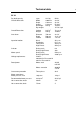
Technical data 2 EX 12 Dry load capacity up to 13,5 kg 30 lbs Overall dimensions Width Depth Height Net weight Dyn.weight 870 mm 900 mm 1302 mm 290 kg 34 1/4'’ 35 15/16'’ 51 1/4'’ 639 lbs 120 lbs./sqft Crated dimensions Volume Weight 1.25 m3 315 kg 44 cu.ft 695 lbs Inner drum Diameter Depth Volume 620 mm 412 mm 120 litre 24 7/16'’ 16 5/16'’ 4.4 cu.ft Speed of rotation Wash Distribution Low extract High extract 48 r.p.m. 75 r.p.m 475 r.p.m. 950 r.p.m.
Technical data 3 EX 22 Dry load capacity up to 22.5 kg 50 lbs Overall dimensions Width Depth Height Net weight Dyn.weight 1000 mm 1102 mm 1412 mm 553 kg 39 3/8'’ 43 3/8'’ 55 9/16'’ 1218 lbs 157 lbs./sqft Crated Dimensions Volume Weight 2.05 m3 588 kg 72.3 cu.ft 1295 lbs Inner drum Diameter Depth Volume 750 mm 500 mm 220 litre 29 1/2'’ 19 11/16'’ 7.8 cu.ft Speed of rotation Wash Distribution Low Extract High Extract 45 r.p.m. 67 r.p.m. 425 r.p.m. 850 r.p.m.
Technical data 4 Outline and dimensions C A D E 6 1 K L 4 3 2 M P B N O G F Q 7 5 1 2 3 4 5 6 7 Opening for electrical cable connection Steam connection (optional) Cold water Hot water Hot water (only EX22) Drain outlet Soap box EX12 mm inches A B C D E F G H J K L M N O P Q R 870 1302 913 792 121 625 570 480 1100 – 240 120 1200 1110 85 203 433 34 1/4 51 1/4 36 31 3/16 4 3/4 24 5/8 22 1/2 18 15/16 43 5/16 – 9 1/2 4 3/4 47 1/4 43 11/16 3 11/32 8 17 R 2664 EX 22 mm inches 1000 1412 1102 9
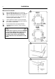
Installation Installation 5 2 The machine is delivered with expansion bolts and other items packed inside the drum. Shipping securities Fig. 2 The machine is shipped with four large metal bracket bolted to the four suspension legs as well as a support between the pulley and the back plate. Prior to installation, follow these steps: • Unpack the machine. Fig. 3 • Remove the lower front panel and the two rear panels. • Remove the support from the pulley at the back of the machine.
Installation • Mark and drill two holes 3/8'' in (8 mm) in diameter and approximately 3 1/2'' in. (90 mm) deep according to the dimensions in figure 5. EX12 866 mm 34 3/32 in. 7 • Insert into the holes the expansion bolts supplied with the machine. Fit the washers and nuts. 33 mm 1 5/16 in. 780 mm 30 23/32 in. 43 mm 1 11/16 in. EX22 996 mm 39 7/32 in. It is of utmost importance that the machine is level, from side-to-side as well as frontto-rear.
Installation Electrical installation Fig. 8 7 8 Although the machines are fitted with thermal overload in the motor windings and separate fuse for the control circuit, a separate three-phase circuit breaker must be installed for all threephase machines. For proper overcurrent protection, check the data plate at the rear of the machine. Also consult local electrical code for special requirements. Fig. 8 Connect L1, L2, L3 and ground wires according to the markings of the terminal block.
Installation 8 Water connection 10 NOTE All plumbing must conform to national and local plumbing codes. Fig. 10 Fig. 11 Incoming water lines do not require non-return valves, as the machine is already fitted with a siphon breaker. However, all incoming lines must be fitted with shut-off valves and strainers. • Water inlets are labelled for hot and cold water connection. • Flush the water system thoroughly and check that the strainer at the machine inlet is fitted correctly. Fig.
Installation Connection of external liquid supply 9 14 Remove cover and cover support over the soap box. Fig. 14 Fig. 15 Fig. 16 Bend all the way back the metal plate in compartment 3. Pull the knobs up and forward. 1. Loosen both knobs so that one side of the metal fingers underneath can slide under the top lid of the machine, within the supply box. 2. Fit the supply injector into the supply box so that both sides are held securely in places by the metal fingers.
Installation 10 Fig. 17 1. Drop the knob into the larger opening in the supply injector lid. 17 2. Tighten securely. Do not overtighten! Do not use pliers or other tools to tighten the knobs! Fig. 18 1. Stretch the multi-rubber ring B and select the correct size ring which will fit snuggly on the chemical tube you are using. Ring A is used for tubes with Ø 1/3" (8 mm). 2. Use scissors or a razor to carefully cut out the proper size rubber ring.
Installation Electrical connection Fig. 19 11 19 At the rear side of the control unit are two quick connectors. When the machine is delivered connector A is connected. When using powder supply, change to connector B. Pump connection Fig. 20 To the right of the incoming power terminal connection block is the connection for pumps. Depending on the number of pumps to be connected, they shall be connected from 1-5 and C (common) on resp. connection. The pumps obtain signals from the timer.
Electro-Lube Dispenser 12 Instruction for setting timing on electro-lube oil dispensing Fig. 21 Fig. 22 Fig. 23 21 Pry off the switch panel cap with a screwdriver. • Under the cap are the switches for time setting. • Set the "Light" and "12M" dip switches to the "On" position. Make certain all other switches are in "Off" position. • The light will start flashing after a few minutes and will continue to flash every 15th to 20th seconds as long as the dispencer is in operation. Fig.
Installation Start-up and safety checklist 13 25 Before initial start-up of a Wascomat washerextractor, the following safety checks must be performed: Fig. 25 • Make sure that all electrical and plumbing connections have been made in accordance with applicable local codes. • Use only flexible water fill and drain hoses of the proper length to avoid sags and kinks. • Make sure the machine is properly grounded electrically.
Installation 14 Function control check-out list 28 In the machine cylinder, you will find the warranty registration card, a copy of the warranty policy and other pertinent material. The warranty card should be completed and sent to Wascomat. All other items should be placed in a safe place for future reference. The machine should be cleaned when the installation is completed, and checked out as detailed below without loading the machine with fabrics: 1.
Safety Rules Safety rules • This machine is designed for water washing only. • Machines must not be used by children. • All installation operations are to be carried out by qualified personnel. Licensed personnel are necessary for all electric power wiring. • The interlock of the door must be checked daily for proper operation and must not be bypassed. • All seepage in the system, due to faulty gaskets etc., must be repaired immediately.
Mechanical and electrical design 16 General Fig. 29 This machine is a free-swinging model i.e. the outer drum and motor bridge are suspended in the machine chassis via a spring suspension with a strong spring in each corner of the machine. Each spring has a shock absorber which dampens the movement of the machine. The inner drum is driven by two motors via a V-belt: one motor for washing and distribution speed and one for extract speed.
Mechanical and electrical design 17 Frame Description Fig. 30 The frame is constructed on the free-swinging principle, i.e. the washing drum is freely and resiliently suspended in the fixed frame. The entire frame is constructed of U-shaped iron beams forming a stable and torsionally rigid structure. The suspension device for the drum unit and motors consists of four posts, one in each corner, each with a robust spring to which the washing drum supports are attached.
Mechanical and electrical design 18 Drum with bearings Description Fig. 31 The inner drum is journalled to the outer drum by two robust bearings in a bearing housing which is bolted to the rear plate. The bearing unit supports the drum without any support being needed at the front. Shaft seals of the V-type, as well as O-rings, seal against leakage. The space between the bearings is packed with grease during assembly. No additional grease is required.
Mechanical and electrical design Safety locking device 19 32 Description Fig. 32 The machine safety locking device includes a safety interlock system which prevents personal injury through the following precautions: • The machine cannot be started until the door is shut. • The door is automatically locked when the machine starts. • It is not possible to open the door until 2-3 minutes have elapsed after the washing program has ended. This ensures that the drum is motionless when the door is opened.
Mechanical and electrical design 20 Function If the machine has not been energised within the last three minutes, the door will remain unlocked. When the machine is energised the door will be locked if a program is activated or if the drum is rotating. Upon completion of a program the door will be unlocked automatically as soon as the drum has stopped rotating.
Mechanical and electrical design Fault location Door does not unlock Conditions: wash program ended and drum at a standstill. Measure the voltage between the following points: 1. X93:2 - X93:3 Should be 0 V DC. If the voltage is 220 V AC, check the rotation guard. 2. X193:1 - X193:2 Should be 0 V DC. If the voltage is 220 V AC, check the rotation guard and the cables between rotation guard and delay unit. 3. X194:1 - X194:4 Should be 220 V AC.
Mechanical and electrical design 22 Rotation guard Description The rotation guard checks that the machine is completely at a standstill before the door can be opened. When the drum has been at a standstill for approx. two seconds the solenoid in the door lock is deactivated and the lock can be opened (provided that the machine has been emptied of water and the programmer has reset). The rotation guard also checks that the drum is revolving when the wash or extraction relays are operating. Fig.
Mechanical and electrical design 23 Control unit Fig. 35 The control unit is mounted under the top panel in the machine. In the unit are the following components: 2-8 Push buttons for manual control. 2 ON/OFF Push button, main supply switch for the machine. 3 Restart push-button switch. When stop is programmed the switch lights up and buzzer goes on. When the switch is depressed the program will continue from where it stopped. 4 Switch for selecting GENTLE ACTION. 5 Switch for opening DRAIN.
Mechanical and electrical design 24 10 Time delay relay for drain. 11 Level switch for high and low level in the drum. For steam and electrical heated machines, the switch is also controlling that there is water in the drum before the heat comes on. 12 Reverser giving start impulses for functions such as reversing, gentle action, etc. 13 Out of balance switch which stops the machine if there is too much unbalance when the machine goes into extraction. 14 Relay for out-of-balance function.
Mechanical and electrical design Relays 25 36 The EX 12 and 22 models employ eight relays. Construction Fig. 36 The body of the relay holding the stationary contacts is made of current-resistant plastic. A solenoid and a contact bank hold the moving contacts. The contacts are spring-loaded to assure the correct contact pressure. The relay is constructed for continuous operation, whether mounted horizontally or vertically.
Mechanical and electrical design 26 Drive motors 37 Description Fig. 37 Both motors, one for wash and distribution and one for extraction, are installed on the same motor bridge. The motors drive the drum and are mechanically connected to each other by V-belts. On the EX 22 there is also an electromechanical clutch. The motors rotate at each others' speed during the wash speed, distribution speed and low extraction speed.
Mechanical and electrical design Repair instructions 27 39 Overheated motor, motor not running • Wait till motor has cooled down. Motor thermal protectors are automatically reset after appr. 30 minutes. Restart. • Possible cause of motor protector releasing repeatedly could be oversensitivity of thermal protector. Very noisy motor • Breakdown of bearings - replace bearings or motor. 180 lbs force Motor running slowly • The motor is probably running on two phases - measure coils on terminal. 1/4 in.
Mechanical and electrical design 28 Supply injection valve 40 Construction Fig. 40 This valve has a single-inlet with three outlets, each with its own solenoid coil. The body is made of heat-resistant polyamid plastic and the solenoids encased in water-tight plastic. The electrical connector terminals are spade lugs. A filter screen on the inlet side prevents dirt from entering the valve. Flow restrictors can be placed at either the inlet or any of the outlets. Operation Fig.
Mechanical and electrical design Repair instructions 29 42 Limescale can block the hole in the valve diaphragm and interfere with the function of the valve. Fig. 42 It is therefore advisable to dismantle and clean the valve at certain regular intervals. The frequency depends on operating conditions and the level of contamination in the water. If the valve does not open • Check that power is supplied to the coil.
Mechanical and electrical design 30 Inlet valve EX 22 Fig. 45 45 The water inlets have brass bodies with a larger cross section of the outlet in order to acheive a shorter filling time for the machine. Construction The valve housing is made of pressed brass. The spring-loaded plunger is made of stainless steel and located at its lower end is a rubber gasket for the pilot valve.
Mechanical and electrical design 31 Soap supply box Fig. 48 The three-compartment soap supply box is located at the top of the machine. Viewed from the front, the compartments are marked with figures 1, 2 and 3. Compartment 1 and 2 are used for adding detergent directly to the wash. Compartment 3 is used for adding fabric softener. All three compartments can be programmed individually.
Mechanical and electrical design 32 Drain valve 49 Description Fig. 49 The drain valve consists of a bracket (1), on which are mounted the motor and gear (2) and diaphragm (3). The rubber diaphragm is resistant to a water temperature up to 100°C (212•F). The installation of a lint trap is not necessary. The machine is equipped with an overflow, which bypasses the drain valve. The drain can be cleaned by removing the drain connection (4) outside of the machine or by removing the rubber diaphragm (3).
Card programming Card programming 33 50 Step no. General Fig. 50 Programmable cards are used to regulate the different phases in a washing process. These are provided with a pattern of 16 ribs with pegs marked with the letters A-Q. The cards are available in two sizes: 80 or 120 steps numbered from 0 upwards. The program controls sense a step of 16 pegs across at one time. The card is fed forward by the program controls motor so that a new step is sensed.
Card programming 34 Fig.
Card programming Instructions for programming Fig. 54 35 54 • The program begins with step 0. Program the step before 0 in the same way as 0 to ensure a correct program start even though the card may be pushed too far into the controls. • Program times Fig. 55 - Each step in the program corresponds to 30 seconds. - The time for heating and filling with water shall not be included in the program time. This also applies when water is added for cool down (rib P).
Card programming 36 Programming example Fig. 57 The following is a description of how the card for normal soiled goods would be programmed. The time required for filling with water and heating must be added, where applicable, to the times stated.
Card programming Pre-wash Time: 4 minutes (steps 0-7) The prewash comprises two phases: 1 Filling and prewash (steps 0-6) Cold water is added (rib O) until high water level is reached (rib N) and is activated during the whole prewash cycle. This adjusts the level automatically while the program is in progress. 2 Draining (step 7) The drain valve opens (rib K). Main wash Time 9 minutes (steps 8-25). The main wash comprises three phases: 1 Filling with water and detergent (step 8).
Card programming 38 Rinse cycle 1-3 These three rinse cycles are identical. Time: 4 minutes and 30 seconds (steps 26-34, 35-43, 44-52). Each rinse cycle comprises three phases: 1 Filling with water and rinsing (steps 26-31, 35-40, 44-49). Filling with cold water (rib O) to high water level (rib N). 2 Draining (steps 32-34. 41-43, 50-52) The drain valve opens (rib K). 3 Spin (steps 33-34, 42-43, 51-52). Spin (rib H and rib L).
Card programming Fig. 58 39 The machine is supplied with a function test card which can be used for testing the different functions after installation. All functions, which can be programmed on the card, are tested.
Procedure for use 40 Procedure for use 59 Preparations Sort the wash according to the washing instructions on labels. Empty pockets and pull up zippers. Open the machine door, insert the wash goods and close the door again. Fig.
Procedure for use Washing Fig. 62 Fig. 63 Fig. 64 Fig. 65 41 62 Turn the dial on the card programmer control panel to the 0 (STOP) position. Insert a programmed card, with the pegs upwards, into the opening below the control. Push the program card in as far as it will go. Press 1-0 (ON/OFF), push-button switch. Start the machine by turning the dial on the programmer control panel to the I (START) position.
Procedure for use 42 Programmed stop 66 If ''Stop with signal'' has been programmed, the machine will stop, a buzzer will sound and a yellow light on the RESTART button will come on. Fig. 66 The machine is started again by pressing the RESTART, push-button. After use Fig. 67 Turn the dial on the programmer control panel to O (STOP) and switch off the machine with the I-O (ON/OFF) switch. CAUTION The door is locked while the wash program is in operation and cannot be opened until 2-3 min.
Procedure for use Manual washing Fig. 69 43 69 Drum rotation To produce drum rotation during manual washing, an unprogrammed card must be inserted in the program controls and the programmer knob turned to I (START). Water filling with detergent and drain Fig. 70 Fill with water by pressing COLD WATER and/ or HOT WATER. Use FLUSHING DOWN DETERGENT to flush down the detergent from compartment 1 (prewash). Water is drained from the machine with DRAIN.
Maintenance 44 Maintenance 71 The carefully considered machine design means that preventive maintenance to reduce faults has been reduced to a minimum. The following measures should however be carried out at regular intervals and to the extent determined by the amount of time the machine is used. Daily Fig. 71 • Clean the door seal and remove detergent residue and check that there are no leaks. • Clean the detergent compartments and wipe down the machine with a damp cloth. Fig.
Trouble shooting Trouble shooting The purpose of the trouble shooting guide is to facilitate the location and correction of the most common machine problems. Before the top panel is removed, power to the machine is to be switched off at the main source or at the separate circuit breaker. At each trouble shooting attempt, the plug in connectors of the control panel should be moved in and out in order to eliminate improper contact due to faulty connection.
Trouble shooting 46 If motor does not operate at wash speed A Check wash relay. B Check motor and V-belt. C Check reversing mechanism. D Review procedures outlined under Section 1 above. If machine runs slowly on wash speed or there is a slapping or thumping noise. A Replace V-belts If a metallic noise can be heard at rear of machine A Tighten pulley on motor shaft If the door is leaking A Check door gasket.
Trouble shooting If water continues to flow without filling machine A Check seating of drain valve. If programmer does not advance A Check synchronous motor on programmer. B Check water level control and the rubber tube leading to same. C Check for leak in drain valve which would prevent machine from reaching its pre-set water level in order to energize the programmer. If machine does not reverse A Check reversing mechanism. B Check auxiliary contact on extract relay.