
Operating instructions


40
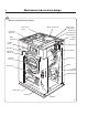
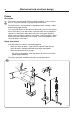
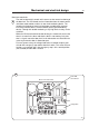
Mechanical and electrical design
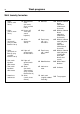
Meaning/cause
Level-sensing device indicates water in drum
when door lock is open. 2.19 Hz
Auxiliary relay for motor indicates that the motor
contactor is activated when the door lock is open
(this error indication pattern does not occur when
the excess-speed-monitoring device is selected).
1.88 Hz
Signals from rotation sensor and auxiliary relay
do not correspond. 1.56 Hz
The control unit sensor circuits indicate fault/
error in drive circuits for door lock including its
wiring. 0.85 Hz
Armament circuits for RE1/RE2 activated
(capacitor C8 charged when it should be
discharged). 0.37 Hz
LED pattern of flashes during normal functioning
Pattern of flashes indicating “OK”, drum at standstill
Pattern of flashes indicating “OK”, drum rotating,
5 Hz
Error indication pattern
4686
Fig.
50
50
Error indication patterns
If the door lock is working correctly, this is indicated by the red LED, by a
pattern of flashes which indicates “OK”. The error indication patterns revea-
led by the LED flash at various frequencies for the various errors or faults.
All error indication patterns have a frequency cycle of 50%, i.e. the LED will
be on half the time, off half the time.
1 second