
Operating instructions


12
Installation
5
6
7
0620
0621
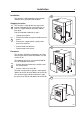
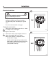
Mechanical installation
• Mark and drill two holes 3/8'' in (8 mm) in
diameter and approximately 3 1/2'' in. (90 mm)
deep according to the dimensions in figure 5.
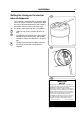
• Place the machine in position. Never lift the
machine by the door or handle.
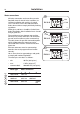
• Check that the machine is level and steady.
Use stainless or galvanized washers between
the machine and the floor.
• Insert the expansion bolts supplied with the
machine. Fit the washers and nuts.
It is of utmost importance that the machine
is level, from side-to-side as well as front-
to-rear. If the machine is not properly
levelled, it may result in out-of-balance
cutout without a real out-of-balance in the
drum.
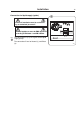
Fig.
5
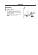
Fig.
7
Fig.
6
4811
870
780
33
4343
790
716
=
=
Front
Front
=
=
1000
910
33
4343
900
830
EX 30 S
EX 50 S