OPERATING & MAINTENANCE MANUAL EX-30 S and EX-50 S 438 9030-13/01 99.20 WARNING: ALL OPERATING AND MAINTENANCE PROCEDURES SHOWN ON THE NEXT PAGE OF THIS MANUAL MUST BE FOLLOWED DAILY FOR PROPER OPERATION OF YOUR WASCOMAT MACHINE. PLEASE ENTER THE FOLLOWING INFORMATION AS IT APPEARS ON THE MACHINE(S) DATA PLATE(S). MACHINE TYPE OR MODEL MACHINE SERIAL NUMBER(S) ELECTRICAL CHARACTERISTICS: ________ VOLTS, _______ PHASE, _______ HZ. MAKE CERTAIN TO KEEP THIS MANUAL IN A SECURE PLACE FOR FUTURE REFERENCE.
II NOTICE TO: OWNERS, OPERATORS AND DEALERS OF WASCOMAT MACHINES IMPROPER INSTALLATION AND INADEQUATE MAINTENANCE, POOR HOUSEKEEPING AND WILLFUL NEGLECT OR BYPASSING OF SAFETY DEVICES MAY RESULT IN SERIOUS ACCIDENTS OR INJURY. TO ASSURE THE SAFETY OF CUSTOMERS AND/OR OPERATORS OF YOUR MACHINE, THE FOLLOWING MAINTENANCE CHECKS MUST BE PERFORMED ON A DAILY BASIS. 1.
SAFETY AND WARNINGS SIGNS Replace If Missing Or Illegible One or more of these signs must be affixed on each machine as indicated, when not included as part of the front instruction panel. LOCATED ON THE OPERATING INSTRUCTION SIGN OF THE MACHINE: CAUTION PRECAUCION 1. Do not open washer door until cycle is completed, operating light is off, and wash cylinder has stopped rotating. 1.
EX-30 S, EX-50 S Contents Introduction .................................................................................... 7 Technical data ................................................................................ 8 Installation .................................................................................... 11 Safety rules .................................................................................. 21 Operating instructions ................................................................
Introduction 7 Introduction The Selecta models washer/extractor has been developed to cover the heavy duty requirements of hotels, motels, nursing homes, hospitals, professional laundries, restaurants, airlines, steamships, schools, colleges and all on-premises laundries where flexibility and quick formula variation, coupled with high quality automatic washing, are required. Fig. 1 The machines are free-swinging, i.e., the drum is moveable and spring suspended in relation to the frame.
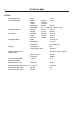
Technical data 8 EX 30 S Dry load capacity up to Overall dimensions Width Depth Height Net weight Floor load 870 mm 34 1/4'’ 790 mm 1325 mm 290 kg 639 lbs 3.3 ± 1.1 kN 790 ± 264 lbs force Crated dimensions Volume Weight 1.25 m3 315 kg 44 cu.ft 695 lbs Inner drum Diameter Depth Volume 620 mm 412 mm 120 litre 24 7/16'’ 16 5/16'’ 4.4 cu.ft Speed of rotation Wash Distribution 24-48 r.p.m. 78 r.p.m Extraction up to 950 r.p.m. During wash During high extract 0.
Technical data 9 EX 50 S Dry load capacity up to Overall dimensions Width Depth Height Net weight Floor load 1000 mm 39 3/8'’ 900 mm 1435 mm 553 kg 1218 lbs 6.0 ± 2.0 kN 1440 ± 480 lbs force Crated Dimensions Volume Weight 2.05 m3 588 kg 72.3 cu.ft 1295 lbs Inner drum Diameter Depth Volume 750 mm 500 mm 220 litre 29 1/2'’ 19 11/16'’ 7.8 cu.ft Speed of rotation Wash Distribution 44 r.p.m. 70 r.p.m. Extraction up to 850 r.p.m. G-factor During wash During High Extract 0.
Technical data 10 Outline and dimensions H K O L C E A P M D 2 1 5 6 3 U 7 B T G J Q N F R 4699 4 1. 2. 3. 4. 5. 6. 7. 8.
Installation Installation 11 2 The machine is delivered with expansion bolts and other items packed inside the drum. Shipping securities Fig. 2 The machine is shipped with four large metal brackets bolted to the four suspension legs as well as a support between the pulley and the back plate. Prior to installation, follow these steps: • Unpack the machine. Fig. 3 • Remove the lower front panel and the two rear panels. • Remove the support from the pulley at the back of the machine.
Installation 12 Mechanical installation Fig. 5 5 • Mark and drill two holes 3/8'' in (8 mm) in diameter and approximately 3 1/2'' in. (90 mm) deep according to the dimensions in figure 5. EX 30 S 870 6 Fig. • Check that the machine is level and steady. Use stainless or galvanized washers between the machine and the floor. 716 Fig. 790 • Place the machine in position. Never lift the machine by the door or handle. 33 • Insert the expansion bolts supplied with the machine.
Installation Connection for liquid supply (option) Electrical installation must be carried out by an authorized personnel! 13 8 L1 L2 L3 N T1 T2 T3 N 1234512 Installed appliances must be EMC approved according to EN 50081-1 and EN 50082-2. Fig. 8 The connections A (1-5) are signals for the liquid supply pumps. The connections B are for Neutral (1) and Phase (2).
Installation 14 Water connections 9 All intake connections to the machine are to be fitted with manual shut-off valves and filters, to facilitate installation and servicing. In certain cases non-return valves will need to be fitted before the machine to comply with local plumbing regulations. EX 30 S Water pipes and hoses should be flushed clean before installation. After installation hoses should hang in gentle arcs. 10 The machine may have between two and four DN 20 (R 3/4") water connectors.
Installation Drain connection Fig. 12 15 12 Connect a 3'’ (75 mm) flexible hose to the drain outlet of the machine. The drain must not have any sharp bends and must slope downward from the machine to assure proper drainage. The outlet must open freely to the main drain. Do not reduce the size of the drain connection from the machine to the waste line.
Installation 16 13 CABLE FROM MACHINE STEAM HOSE APPROVED FOR min. 0,1 MPa max. 0,8 MPa SEAL WITH TEFLON OR SIMILAR CONNECTION STEAM INJECTOR IN MACHINE For rebuilding look at the wiring diagram of the machine.
Installation Steam connections (optional steam heating) 17 14 Steam pressure required: • minimum 7 PSI • maximum: 110 PSI • recommended: 40-85 PSI A steam valve for this machine type is fitted separately in a bracket on the upper rear cover plate. The steam valve, hose and filter are supplied with the machine. Steam-flush all pipes and hoses before connection. Installation instructions: • Install rear cover plates. Fig. 14 • Install steam valve bracket and valve.
Installation 18 Electrical installation 15 Electrical installation must be carried out by an authorized personnel! Mount a multi-pole switch prior to the machine to facilitate installation and service operations. L1 L2 L3 N T1 T2 T3 N 1AC The connecting cable should hang in a gentle curve. Fuse size can be found on next page. Single-phase connection: Fig. 15 Connect the earth and other two wires as shown in example "1AC" in the figure. Three-phase connection: Fig.
Installation Setting the timing on the electrolube oil dispenser 19 17 This machine is equipped with an electronic oiler which lubricate the seals on a timed bases. With the rear panel removed locate the oiler, which is attached to the base frame at the lower rear. Fig. Pry off the switch panel cap with a screwdriver. 17 Fig. • Under the cap are the switches for time setting. 18 Fig.
Installation 20 Start-up and safety checklist 20 Before initial start-up of an EX 30 S/EX 50 S washer, the following safety checks must be performed: 2 3 4 5 6 7 8 1 • Make sure that all electrical and plumbing connections have been made in accordance with applicable local codes. 9 0 • Use only flexible water fill and drain hoses of the proper length to avoid sags and kinks. • Make sure the machine is properly grounded (electrically).
Safety rules Safety rules • This machine is designed for water washing only. • Machines must not be used by children. • All installation operations are to be carried out by qualified personnel. Licensed personnel are necessary for all electric power wiring. • The interlock of the door must be checked daily for proper operation and must not be bypassed. • All seepage in the system, due to faulty gaskets etc., must be repaired immediately.
Operating instructions 22 Operating instructions The Emerald Series program unit controls the various functions of the machine in a certain time sequence with the aid of seven built-in standard programs. The standard programs can also be modified by selecting various options. By selecting options, the user has access to programs for all types of wash loads and degrees of soiling. Fig.
Operating instructions Washing Fig. 23 23 • Press the button for the desired program. 24 • Now the LEDs alongside the program symbols will show what the selected program consists of. Fig. • Press the button(s) for any options required. Fig. 23 1 Hot 5 Perm Press 2 Warm 6 Quick-Wash 3 Cold 7 Heavy Soil 4 Delicate 25 START 3426 Fig. 26 Fig. Gentle actions consists of 6 seconds rotation, as opposed to 18 seconds pause and 6 seconds pause and 14 seconds rotation for Normal action.
Operating Instructions 24 Fig. 28 • Now the display will show the clock symbol and two digits. The two digits are the time left before the wash will be finished. 28 The two digits indicating time left will not appear when the machine is first installed. Each program needs to have been used at least once before the time left will be displayed. 3141 • For 5 minutes immediately after START is pressed the colon character (: ) will flash on the display.
Operating Instructions For coin-operated machines Fig. 31 Fig. 32 25 31 Select a wash program, then insert the number of coins corresponding to the figure shown on the display. As each coin is added the machine counts backwards towards 00 on the display. The machine will not start until the display shows 00. • Press the START button. • Now the display will show the clock symbol and two digits. The two digits are the time left before the wash will be finished.
Operating Instructions 26 Rapid advance 34 Whole steps in programs can be skipped using rapid advance. Fig. 34 START • Press and hold the START button until the program indicator LEDs have moved past the program steps you wish to skip. Program end Fig. 35 Fig. 36 After final extraction, the LED by the "doorlock delay" comes on. This shows that the door lock will shortly be unlocked.
Programming Coin-operated machines 27 37 In coin-operated machines the prices for the various programs have to be programmed in. Values from the coin mechanism (the accumulated value) can be read out with the aid of the service program. If a machine is fitted with a coin mechanism after its original installation the relevant electronic circuitry will have to be activated before the prices can be programmed in.
Programming 28 Codes 91 and 92 are used to store the values for coin slots 1 and 2. For mechanisms with only one slot, only code 91 is used. 39 The values to be stored are the ratio of one coin to the other. For example: if the coin slots are for a 10 cent coin and a 50 cent coin. The value 10 should be stored under code 91, and the value 50 should be stored under code 92. Fig. 39 • Enter code 91 using the buttons which have become number keys 9 and 1. 2275 The display will now show 91. Fig. 40 Fig.
Programming Price programming: 29 44 • Press the relevant wash program selector button. Fig. 44 When programming the price of a wash program plus options, press both the relevant program selector button and the option button. • Keep the price-programming button activated. Now the display shows 00 plus the coin symbol. 2273 • Enter the price via the numerical key functions. The START button can be used to enter 0. • Release the price-programming button.
Wash programs 30 Hospitality wash formulas For hotels/motels, restaurants, retirement communities, schools and universities, commercial and institutional laundries.
Wash programs 31 Healthcare wash formulas For nursing homes, hospitales and medical center.
Wash programs 32 Shirt laundry formulas 1 Shirts (starch, cold rinses) 1A Short formula shirts (no starch) (may use with 5 or 6) 1B Delicates 1AB White or colored blend table linen (with bleach, no starch) 2 Shirts (starch, warm rinses) 2A Heavy soil shirts (one starch injection) 2B Mops 2AB White or colored blend table linen (with bleach and starch) 3 Shirts (no starch) (may use with formula 5 or 6) 3A Shirts (pause for starch) 3B Extra heavy soil – no – iron fabrics 3AB White or colored 100%
Mechanical and electrical design Maintenance This machine has been carefully designed to minimize preventive maintenance. However, the following routine operations should be performed at regular intervals (depending on how much the machine is used). Daily • Clean detergent residue from the door seal and check that the door does not leak. • Clean the detergent compartments and wipe down the machine with a damp cloth. • Check that the drain valve does not leak.
Mechanical and electrical design 34 45 Machines with permanent programs Motor control unit Inlet valves, water Steam valve (obscured) Automatic control unit Detergent dispenser Inward power supply terminals PCU board Control panel Heating relay Door lock 95 Transformer 60 60 40 40 Imbalance switch 60 30 Machine door Outer drum Motor Elements Spring suspension Oil lubrication Drain valve Frame Damper 4679
Mechanical and electrical design The washing machines are controlled by a microprocessor program unit. This provides several major advantages: • The control of times, levels and temperatures takes place with considerable precision and flexibility • The large character display provides detailed information in clear text about the different wash programs, the machine's different activities, relevant wash times and temperatures.
Mechanical and electrical design 36 Frame Description Fig. 46 The frame is constructed on the free-swinging principle, i.e. the washing drum is freely and resiliently suspended in the fixed frame. The entire frame is constructed of U-shaped iron beams forming a stable and torsionally rigid structure. The suspension device for the drum unit and motors consists of four posts, one in each corner, each with a robust spring to which the washing drum supports are attached.
Mechanical and electrical design 37 Drum with bearings Description Fig. 47 The inner drum is journalled to the outer drum by two robust bearings in a bearing housing which is bolted to the rear plate. The bearing unit supports the drum without any support being needed at the front. Shaft seals of the V-type, as well as O-rings, seal against leakage. The space between the bearings is packed with grease during assembly. No additional grease is required.
Mechanical and electrical design 38 Description The machine door lock consists of the following: Fig. 48 • The locking unit, located behind the front panel below the detergent dispenser. The unit consists of a solenoid which locks the door, and two microswitches. Switch S4A indicates that the door is locked and switch S3 indicates that the door is closed. • The door lock control unit, located in the automatic control unit. This unit consists of a circuit board for monitoring door lock functioning.
Mechanical and electrical design 39 Door lock control unit Fig. 49 The sole function of this control unit is to oversee the correct functioning of the door lock. The CPU board receives information from the motor control unit about motor rotation, and has its own level-monitoring device. The control unit also detects water level and motor speed through separate level measurement devices and the rotation guard (speed-monitoring device).
Mechanical and electrical design 40 Error indication patterns Fig. 50 If the door lock is working correctly, this is indicated by the red LED, by a pattern of flashes which indicates “OK”. The error indication patterns revealed by the LED flash at various frequencies for the various errors or faults. All error indication patterns have a frequency cycle of 50%, i.e. the LED will be on half the time, off half the time.
Mechanical and electrical design 41 Program control unit Control system transformer T10 Fig. 51 The control system transformer is used to provide the voltage feed for the circuit boards. The transformer supplies 12 V on its secondary side, and can be adapted to suit any of four different primary voltages by moving a strap. The transformer should normally be connected for a primary voltage of 230 V. Switching for different power supply voltages takes place at transformer T1.
Mechanical and electrical design 42 Imbalance switch Description Fig. 52 The imbalance switch is a safety feature which protects the machine from damage during extraction caused by uneven distribution of the wash load. The imbalance switch consists of a microswitch and a switch arm, mounted on the left-hand front pillar of the frame. If the inner frame moves outside a certain range, it will actuate the microswitch via the switch arm.
Mechanical and electrical design 43 Motor Description Fig. 53 The motor is mounted inside a motor mounting unit beneath the outer drum. It drives the inner drum via a drive belt. The drive belt tension is adjusted with the aid of two retaining screws on the side of the motor mounting unit. See the section “Belt tension” in this chapter. Electrical connection for the motor is by quick-connector.
Mechanical and electrical design 44 Motor control unit E10 54 X312 X301 X302 X304 X308 LC2 X311 4744 Fig.
Mechanical and electrical design 45 Motor control unit The motor control unit communicates with the PCU board via a serial duplex interface. With the aid of the MCU, the PCU board can not only control the speed the motor is to have at any given moment, but also control the acceleration and deceleration rates the motor will use to reach the speed commanded. The MCU constantly relays information back to the PCU board on current operating status, e.g.
Mechanical and electrical design 46 For the 220 l machine there is a cooling fan on the MCU, on account of its higher wattage. The fan starts up automatically when the heat sink reaches a temperature of approx. 65°C, which can arise during extraction if the load is unfavourable or if the ambient temperature is high. When the machine power supply is first switched on the fan operates for a short time.
Mechanical and electrical design X308: Imbalance input The function of the imbalance input is to stop the motor if the drum’s movement is too great. (The imbalance switch is normally open.) When the imbalance switch is activated (closes) a voltage of 96 - 276 V AC is supplied to the MCU. The MCU detects that imbalance has arisen and stops the motor. Input voltage: 120 V-20 % (=96 V) - 240 V+15 % (=276 V), 50/60 Hz The imbalance input receives its supply from Input lock sequence (X302). Current: Max. 0.
Mechanical and electrical design 48 Error indication patterns If a fault or error occurs in the motor or motor control unit, the MCU sends an error signal to the PCU board. In addition to an error code showing on the display, errors/faults are revealed by the flashing of a yellow LED on the MCU board. The table below shows how to identify the error/fault on the basis of the flashing pattern of this LED. Fig. 56 Fig.
Mechanical and electrical design 49 Fault-finding There are fault-finding charts for all error codes. 57 X312 X313 X301 X302 X311 X308 X304 Yellow LED Green LED Error indication patterns, green LED The green LED on the MCU board is normally lit except for a brief pause approx. once every five seconds (pattern which indicates “OK”). Fig. 58 When the microprocessor for the PCU is removed from the machine or has reset status, the LED will be lit without flashing.
Mechanical and electrical design 50 Extraction During extraction, the motor speeds follow an extraction sequence which is always the same. This extraction sequence is used for all WE/MP machines and for standard programs 991-999 for CLARUS machines. Fig. 59 The table shows the extraction speeds during the various phases of the sequence, for various drum volumes. The extraction sequence is as follows: Phase 1. Distribution period of 40 seconds, with imbalance sensing.
Mechanical and electrical design Imbalance measurement At the start of every extraction sequence the system monitors variations in the motor torque while the drum is operating at distribution speed. If these variations are too great, it indicates that the load is unevenly distributed in the drum. At this point extraction is halted, the motor speed is reduced to wash speed and a fresh attempt to begin extraction starts. This procedure will be repeated up to three times per extraction.
Mechanical and electrical design 52 Belt tension Fig. 60 Fig. 61 60 The tension of the drive belt is preset at the factory. When checking belt tension, or after replacing components which affect belt tension, follow the instructions contained in the illustrations. Max. 9 mm Correct belt tension is important. The tension should always be checked as part of service and maintenance. 7 mm F = 30 N (EX-30 S) F = 40 N (EX-50 S) X = 7 mm when belt is new. Max. 9 mm on subsequent checks of same belt.
Mechanical and electrical design Drain valve 53 62 Description Fig. 62 Fig. 63 The drain valve is a motor-operated diaphragm valve which allows rapid emptying thanks to its large cross-section. This is a self-clearing design, so there is no need for a lint filter. Main parts of the valve: • motor plus gear • piston rod with trapezoidal thread, plus piston and return spring • rubber diaphragm • connections for water filling, overfilling, drain In its open state, the valve is not energised.
Mechanical and electrical design When the motor is activated and begins to rotate, the piston rod is turned upwards via the gear, the diaphragm is pressed upwards with the piston and presses against the valve seat: the valve closes. The connection for overfilling is connected to the upper part of the wash drum, water and foam are diverted straight to the drain if the intake valves or level control should malfunction.
Mechanical and electrical design 55 Tensioning of return spring With the valve housing removed: - Turn the return spring so that the “tongue” of the spring is resting against the stop screw. - Position the valve housing over the return spring so that the pin on the spring will fit into the recess on the piston rod. (Note: the piston rod should be installed so its recess is aligned along the housing.) - Then turn the housing one turn clockwise. (This will screw the pin of the spring into the piston rod.
Mechanical and electrical design 56 Heating 65 Description Fig. 65 Fig. 66 The machine elements are in the lower part of the outer drum, accessible from the machine front. They are switched in by heating relays, controlled by the program control unit. For input voltage 400-440 V one heating relay is used (K21), and for 208-240 V, two are used (K21 and K22).
Mechanical and electrical design To replace an element • Switch off the power supply to the machine at the main switch/wall switch and check that the machine is isolated from the power supply. Remove the front panel. • Note exactly how the elements electrical connections are arranged, then disconnect them. • Undo the nut between the element’s connections and turn the screw a half turn. • Remove the inspection cover in the inner drum. Turn the drum so the opening is at the bottom.
Mechanical and electrical design 58 Weighing equipment Description Fig. 67 67 Scale unit The weighing equipment comprises the following units: • A scale unit located inside the machine’s right side panel • Four load cells, one in each corner of the frame • Wiring The weight of the wash load is registered by the four load cells, which send analogue signals to the scale unit. In the scale unit the signals are processed and converted to a weight value in an analogue-digital converter.
Mechanical and electrical design Inlet valve, detergent 59 68 Construction Fig. 68 The valve has a single-inlet with either one, two or three outlets, each with its own solenoid coil. The body is made of heat-resistant polyamid plastic and the solenoids encased in water-tight plastic. A filter screen on the inlet side prevents dirt from entering the valve. Flow restrictors can be placed at either the inlet or any of the outlets. Operation Fig.
Mechanical and electrical design Maintenance instructions 70 Lime scale can block the hole in the valve diaphragm and interfere with the function of the valve. Fig. 70 It is therefore advisable to disassemble and clean the valve at certain regular intervals. The frequency depends on operating conditions and the level of contamination in the water. Trouble shooting If the valve does not open ventilating hole pilot valve • Check that power is supplied to the coil.
Mechanical and electrical design Inlet valve Fig. 73 61 73 The water inlets have brass bodies with larger cross section of the outlet in order to achieve a shorter filling time for the machine. Construction Fig. 74 The valve housing is made of pressed brass. The spring-loaded plunger is made of stainless steel and located at its lower end. Operation The valve is automatically operated by means of a rubber diaphragm and a pilot valve in exactly the same way as the supply injector valve.
Mechanical and electrical design 62 Soap supply box Fig. 75 The three-compartment soap supply box is located at the top of the machine. Viewed from the front, the compartments marked with figures 1, 2 and 3 are used as follows: Compartment 1 This compartment is used for adding detergent at the beginning of the Prewash cycle. Powders may be loaded immediately; for liquids, wait until the display shows an arrow and the compartment flushes with water.
Mechanical and electrical design Drain valve 63 76 Description Fig. 76 The drain valve consists of a bracket (1), on which are mounted the motor and gear (2) and diaphragm (3). The rubber diaphragm is resistant to a water temperature up to 100°C (212°F). The installation of a lint trap is not necessary. The machine is equipped with an overflow, which bypasses the drain valve. The drain can be cleaned by removing the drain connection (4) outside of the machine or by removing the rubber diaphragm (3).
Mechanical and electrical design 64 Electronic program control unit Description Fig. 77 The program control unit is electronic and consists of a circuit board with components. On one half are the microprocessor, program memory (EPROM), power supply circuits, temperature and level control devices and so on. On the other half are the relays and interference suppression components. The program control unit has the following inputs and outputs: • Inputs reacting to push-buttons on the control panel.
Mechanical and electrical design Operating time, accumulated coin value, EPROM no. 65 78 The machine’s built-in service program can be used to check the machine’s accumulated operating time, the accumulated coin value (for coinoperated machines), and the program EPROM part number. Accumulated operating time To check during normal operation Fig. The machine needs to be actually operating 78 (program selected and started).
Mechanical and electrical design To check in service mode Fig. 81 81 Enter code 43. The first two digits of a four-digit number will now be displayed, e.g. 13. Enter code 44. The last two digits of a four-digit number will now be displayed, e.g. 47. Code 43 + This means that the machine’s accumulated operating time is 1,347 hours.
Mechanical and electrical design To check in service mode Fig. 82 67 82 Enter code 41. The first two digits of a four-digit number will now be displayed, e.g. 06. Enter code 42. The last two digits of a four-digit number will now be displayed, e.g. 58. This means an accumulated coin value of 658 currency units or 658 tokens. In other words, it shows that 658 currency units or tokens have been inserted into the coin mechanism up until the time of the check.
Mechanical and electrical design Program EPROM part no. (check in service mode) Fig. 83 Enter code 51. The letter A and two digits will be displayed, e.g. A47. ”A” denotes part no. (article no.). 83 Code 51 + Enter code 52. The display will show (e.g.) 195. Enter code 53. The display will show (e.g.) 803. Enter code 54. The display will show (e.g.) 480. Code 52 When these digits are put together they make up the full part number: + A471 958034.
Mechanical and electrical design Level control Description 69 84 The "level control", which is located on the circuit board, is a pressure switch which monitors the different water levels in the drum by sensing the air pressure in a tube which is connected to the bottom of the drum. As the water rises in the drum, the air inside the tube is compressed and at a set pressure ("cut-out-level") the micro-processor cuts out water filing.
Service program 70 Built-in service program 86 The machine has a built-in service program to facilitate function checking and fault-finding. Service switch This program may only be used by trained and authorized service personnel. To switch on service mode • Remove the machine top and the cover for the program unit circuit board. • Press the service switch. This switch is on the left-hand edge of the circuit board when viewed from the machine front.
Service program Error codes Given below is a brief summary of all the error codes and their causes. Error Code Cause 11 Detergent signal 1, liquid detergent. 12 Detergent compartment 2, cold water /Detergent signal 2, liquid detergent. 13 Detergent compartment 3, cold water /Detergent signal 3, liquid detergent. 14 Detergent compartment 2, hot water /Detergent signal 4, liquid detergent. 15 Detergent signal 5, liquid detergent. 16 Hot water in drum. 17 Detergent compartment 1, cold water.
Service program 72 Error Code 37 Cause LED test 41-42 Coin mechanism (see Page 39, Program control unit). 43-44 Counter (hours) for accumulated operating time (see Page 39, Program control unit). 45 51-54 Last error code flagged. Program EPROM part number (see Page 39, Program control unit). 91 Coin value, coin slot 1. This is set using the priceprogramming switch (see Page 39, Program control unit). 92 Coin value, coin slot 2.
Trouble shooting 73 Trouble shooting If the power supply to the machine should be cut while it is operating, the program unit has a memory which stores the program selected for about 3 to 5 minutes. Within this period the machine will restart automatically once the power supply is restored. Indication of faults/errors Fig. 89 Faults/errors in the program or machine are indicated by a numerical error code followed by the letter E flashing on and off on the control panel display.
Trouble shooting 74 Error codes Given below is a brief summary of all the error codes and their causes. Starting on page 5 of this section there are fault-finding charts for all error codes. At the end of the chapter there are also charts for faults which do not generate error codes. Error code Cause 01E Water level not reached within set time. Take necessary action. Press START again. 02E Door status switch open during program operation. Take necessary action. Press START again.
Trouble shooting 75 Error codes which may arise on the control panel display Error code/symptoms Fault-finding 01E Acknowledgement signal for water level not received within time allowed. Check that the manual water valves (taps) are open. Taps turned on. Taps turned off. Cause/Action Open taps. Press START again. 2316 6 5 4 3 2 1 X80 Y14 2 X81b 1 Y12 Y13 4 3 Restart the program and use rapid advance to get to main wash. Check that the machine is filling with water.
Trouble shooting 76 Error code/symptoms Fault-finding 02E Door status switch open during program operation. Open door. Close door and try to restart the machine. Error code returns No error code Cause/Action Transient fault in door lock or program PCB. Set program control unit to service mode (see ”To switch on service mode”). The door status switch will now be indicated by the LED (illustrated). Press in the door status switch manually and check if this is indicated by the LED. LED does not light.
Trouble shooting 77 Error codes which may arise on the control panel display Error code/symptoms Fault-finding 03E The lock has not locked the door within the set time. Open door. Close door and try to restart the machine. Error code returns No error code Cause/Action Transient fault in door lock or program PCB. Start service program and activate door lock (code 23, press START). Check input voltage to door lock, PCB connector X71 between terminals 1 and 2. Voltage correct. Voltage absent or wrong.
Trouble shooting 78 Error codes which may arise on the control panel display Error code/symptoms Fault-finding 06E Water level signal above parameter set, on program start-up. Are there water in the drum? Yes Cause/Action No Disconnect the level tube from the program PCB. Turn the machine’s wall switch off and on again. Start a program. Error code 06E No error code or error code 01E Connection level tube 3350 Turn the machine’s wall switch off.
Trouble shooting 79 Error codes which may arise on the control panel display Error code/symptoms Fault-finding Cause/Action 07E Water level signal above parameter set for safety, during program. Turn the machine’s wall switch off and on. Start a program. Error code 06 No error code Transient fault or water has been added manually. Is there a valve still drawing water? Yes No Turn the wall switch off and on. Disconnect level tube from level sensing device on PCB. Start a program.
Trouble shooting 80 Error codes which may arise on the control panel display Error code/symptoms Fault-finding Cause/Action 10E The water level is above the safety level set for after drain. Is water visible in the drum? Yes No Remove the water drain valve from the drum. Is there water at the bottom of the drum? Yes No Disconnect the level tube from the program PCB. Turn the machine’s wall switch off and on again. Start a program.
Trouble shooting 81 Error codes which may arise on the control panel display Error code/symptoms Fault-finding 12E The program control unit cannot read the program EPROM. Turn the machine’s wall switch off and on again. Start a program. Error code returns No error code Cause/Action Transient fault. No action required. Unscrew the program control unit PCB. Remove the EPROM, then refit the same one. Check that the EPROM is turned the right way and that all its leg connectors enter the holder correctly.
Trouble shooting 82 Error codes which may arise on the control panel display Error code/symptoms 14E Level system not temperature-calibrated Fault-finding Cause/Action When START is pressed wash programs will run, but the water level will not be optimally adjusted. Turn the machine’s wall switch off and on again. Start a program. Error code returns No error code Transient fault. No action required. Replace program control unit PCB.
Trouble shooting 83 Error codes which may arise on the control panel display Cause/Action Error code/symptoms Fault-finding 17E Door status switch open, even though the door lock is locked. Turn the machine’s wall switch off and on again. Start a program. Error code returns No error code Set program control unit to service mode. The door status switch and door lock switch will now be indicated by the LEDs shown left.
Trouble shooting 84 Error codes which may arise on the control panel display Error code/symptoms Fault-finding 20E Interlock signal absent at motor control unit during program operation. Turn the machine’s wall switch off and on again. Start a program. Error code returns No error code Cause/Action Transient fault. No action required. X302 Check the voltage between terminals 1 and 2 at PCB connector X302 on motor control unit. The voltage should be 120/230 V when the door is closed and locked.
Trouble shooting Error code/symptoms Fault-finding Machine completely ”dead”. Display blank. Turn the machine’s wall switch off and on again. Fault persists. Machine working 85 Cause/Action Transient fault. No action required. Check fuses F11, F12, F21 and F22. Fuses sound Fuse fault Change fuse(s) and check functioning. Check that the input voltages to the PCB are correct.
Trouble shooting 86 Error code/symptoms Fault-finding Display blank, but machine is working otherwise. Turn the machine’s wall switch off and on again. Fault persists. Machine working Cause/Action Transient fault. No action required. F2, F3 Display Check glass-tube fuses F2 and F3 on program control unit PCB. Rating: 1 A/250 V. Fuses sound Fuse fault Change fuse(s) and check functioning. 2316 7 1 Check that input voltages to PCB are correct.